Table of Contents
Advertisement
Quick Links
Alter ELETTRONICA s.r.l.
15033 Casale Monferrato (AL) – ITALY
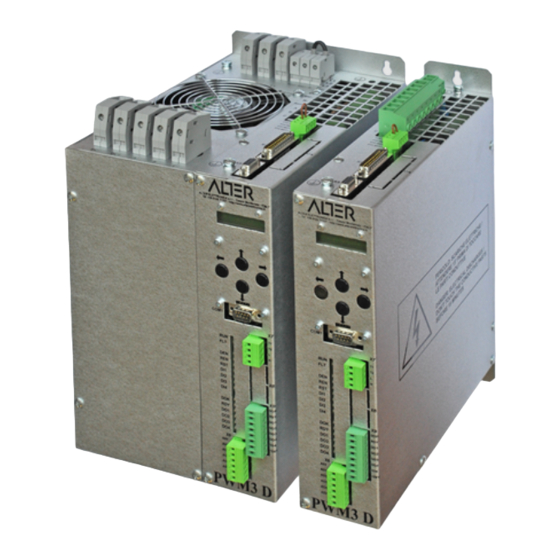
PWM3D-000
PWM3D-010
Drive 4 quadrants series PWM Digital
for asynchronous motors with transducer
Instructions
manual
Instructions
manual
Compatible with Firmware V
Compatible with Firmware V
/
Type No.: ___
___ ___ ___
:
91/104
- Version
9.2
:
91/104
- Version
9.2
Combined with the drive:
Serial No.: ___ ___ ___ ___ ___
- Date:
26/05/2021
- Date:
26/05/2021
9.x
9.x
Advertisement
Table of Contents

Related Manuals for ALTER PWM3D-000

Summary of Contents for ALTER PWM3D-000
- Page 1 Alter ELETTRONICA s.r.l. 15033 Casale Monferrato (AL) – ITALY PWM3D-000 PWM3D-010 Drive 4 quadrants series PWM Digital for asynchronous motors with transducer Instructions manual 91/104 - Version - Date: 26/05/2021 Instructions manual 91/104 - Version - Date: 26/05/2021 Compatible with Firmware V...
-
Page 2: Table Of Contents
6.2 Green LEDs – Internal states and outputs....................76 6.3 Red LEDs – Alarms..........................77 6.4 Alarm messages............................77 6.5 Reporting messages..........................81 6.6 Diagnostic menu............................83 7 Annexes................................84 7.1 Led Summary Table..........................84 8 Mechanical characteristics..........................85 8.1 Size 1................................85 8.2 Size 2................................86 8.3 Size 3................................87 Alter Elettronica s.r.l. -
Page 3: Safety Information
Safety information 1 Safety information Read this manual carefully before using the drives PWM3D-000. Keep the manual carefully and in a place of easy access in order to consult it later in case of need. Make sure this manual is delivered to the end user. -
Page 4: Warnings
Avoid penetration of water or other fluids inside the drive. • For wiring use appropriate cables, possibly shielded. 1.4 Directives, trademarks and standards The drive PWM3D-000 complies with the following industrial standards: Standard/Marking Description CEI EN 60204-1 Low voltage safety directive, 73/23/EEC. -
Page 5: Identification Of The Product
2.2 Declaration of conformity The ALTER Elettronica S.r.l. declares that, in the conditions specified in this document, the drives (CDM) model " PWM3D-000“, are in conformity with the Community directives EMC, including the latest amendments, with the relative Italian transposition legislation and the Community directives Low Voltage, including the latest amendments, with the relevant Italian transposition legislation. -
Page 6: Model Encoding
Identification of the product Instruction manual 91/104 V9.2 2.4 Model encoding The following tables indicate the encoding method for ordering a model drive: PWM3D-000 Maximum voltage Current service Drive model Options output continuous output PWM3D- 010= 10Arms 016=16Arms 021= 21Arms... -
Page 7: Technical Characteristics
30 seconds. [2] Dimensions and masses on page 63 and page 68. [3] The filter shall be mounted when the PWM3D drives are used in First Ambient, to meet the EMC compatibility require- ments. Alter Elettronica s.r.l. - Page 8 To have more exact values it is necessary to know the actual conditions of use of all motors. Contact the ALTER Technical Office to examine special cases. 3.2.2 Current absorbed with DC-BUS power supply...
- Page 9 Over-current in the drive. – Transducer failure mounted on the motor. – Failure or overload in the recovery circuit on resistance. – Failure in the drive. – Overload or short circuit of digital outputs. – Wrong settings. Alter Elettronica s.r.l.
- Page 10 Protect the supply with no.2 delayed fuses with a rated current 1A. 3.2.4.3 POWER The power supply of the PWM3D-000 drive can be supplied in the following ways: • A three-phase ground neutral network with a chained voltage within the limits indicated on the drive plate (see "Identification plate on page 5.
-
Page 11: Installation
Instruction manual 91/104 V9.2 Installation 4 Installation Drawing 1 Connection to a three-phase power line (PWM3D-000 only) Alter Elettronica s.r.l. -
Page 12: Preliminary Operations
Do not use terminal blocks but only shielded connectors for signal and power shielded cable junctions. • Mounting noise suppressors (off for a.c./diodes for D.C.) parallel to the coils of all contactors, relays, solenoid valves, single- phase motors, three-phase motors, etc. Alter Elettronica s.r.l. -
Page 13: Motor Wiring
Using the following formula, calculate the value of the “electric time constant " of the motor; If the result is less than 10msec, an in- ductance between the motor and the drive shall be mounted. In case of doubt or for further information, please contact the ALTER Technical Office. -
Page 14: Signal Connections
(twistates) and shielded cables. For the sizing of the various elements described in this paragraph it is advisable to contact the ALTER technical service. In the case of drive size 1 this connection is on the X2 connector; instead, with a drive size 2 you have to use the special screw termin- als. - Page 15 1 PTC-RES- Connect the thermistor mounted to the resistors of external clamps, otherwise leave the bridge connected (only 2 PTC-RES+ for PWM3D-000). 3 PTC-MOT- Connect the thermistor mounted in the motor. NOTE: this contact is also available in the X4 connector.
- Page 16 Further information can be found in paragraph ”Alarm messages“ on page 77. “Ready“ digital output. It signals that the drive is ready for operation and is therefore able to perform the commands. See also paragraph ”RDY (Ready)“on page 76. Alter Elettronica s.r.l.
- Page 17 Tensions between: AI1+ and A0V, AI1- and A0V, AI1+ and AI1- = ±10V max. 10KΩ input resistance. AI1- Cold pole of the analog input 1. 0V analog. The analog 0V is connected to the drive case. Analog input 2 (resolution 11 bit + sign) programmable. Voltage between AI2 and A0V = ±10Vcc max. Alter Elettronica s.r.l.
- Page 18 Drawing 9 Connection of a numerical control (or a PLC) with bal- anced output to provide the speed reference. Drawing 10 Connecting a potentiometer to a generic analog input to provide a reference. Drawing 11 Alter Elettronica s.r.l.
- Page 19 Below are some drawings to explain the correct connections to the X12 connector: Connection of contacts to send commands to the digital inputs of the drive. It is necessary to connect the D0V to 0V. Drawing 13 Alter Elettronica s.r.l.
-
Page 20: Commands Starting Sequence
1. Give 230Vca service power supply on the X10 connector. 2. In the case of model PWM3D-000 when the DOK output switches to ON status and the green LED DOK turns on, you can give the three-phase/monofase power supply on the terminals L1, L2, L3 or D.C. power supply on the DC-BUS if this mode has been selected (see Drawing 2 on page 12 and menu "Power supply from“... -
Page 21: Commissioning
Level 4 QUICK SETUP MOTOR PARAMETERS SELECTED GEAR menu at level 1 menu at level 2 [...] MOTOR TYPE [...] LowSpd NOMINAL VOLTAGE: [...]V CONT.SERV.CURR.: [...]A MAXIMUM CURRENT: [...]A NOMINAL FREQUEN: [...]Hz MOTOR POLE [...] Alter Elettronica s.r.l. - Page 22 [...] RESOLVER POLE PAIR: [...] AUTOTUNE MODE [...] Disabled Optional param. NOMINAL SPEED menu at level 3 [...]RPM FDBK DIRECTION [...] normal Magnet.Current [...]A Stator resist. [...]Ω 0.00 Magnetic Induct. [...]mH 0.00 Leakage Induct. [...]mH 0.00 Alter Elettronica s.r.l.
- Page 23 [...] 1.0000 An.Inp.1 Gain 2: [...] 0.0500 An.Inp.1 Offset: [...]% 0.00 An.Inp.1 Sign: [...] Normal An.Inp.1 Value: [...]% SPEED RAMP Time: [...]Sec MEMO PARAMETERS ==== SAVE ==== menu at level 1 [...] === RESTORE == [...] Alter Elettronica s.r.l.
- Page 24 3 [...] NotUsed An.Inp.2 Gain: [...] 1.0000 An.Inp.2 Offset: [...]% 0.00 An.Inp.2 Value: [...]% ANALOG INPUT 3 An.Inp.3 Dest: menu at level 3 [...] NotUsed An.Inp.3 Gain: [...] 1.0000 An.Inp.3 Offset: [...]% 0.00 Alter Elettronica s.r.l.
- Page 25 3 [...] Mot.Load An.Out.1 Value: [...]% An.Out.1 Gain: [...] 1.0000 An.Out.1 Offset: [...]% 0.00 An.Out.1 Abs: [...] True ANALOG OUTPUT 2 An.Out.2 Source: menu at level 3 [...] Mo.Speed An.Out.2 Value: [...]% An.Out.2 Gain: [...] 1.0000 Alter Elettronica s.r.l.
- Page 26 3 [...] OverLoad An.Out.4 Value: [...]% An.Out.4 Gain: [...] 1.0000 An.Out.4 Offset: [...]% 0.00 An.Out.4 Abs: [...] True DIGITAL INPUTS DIGITAL INPUT 1 Dig.Inp.1 Dest: menu at level 2 menu at level 3 [...] Rev.Spd Alter Elettronica s.r.l.
- Page 27 menu at level 3 [...] Pos.Enab Dig.Inp.4 Sign: [...] Normal Dig.Inp.4 Value: [...] DIGITAL OUTPUTS DIGITAL OUTPUT 1 Dig.Op.1 Source: menu at level 2 menu at level 3 [...] Zero Spd Dig.Op.1 Value: [...] Alter Elettronica s.r.l.
- Page 28 Dig.Op.3 Sign: [...] Normal DIGITAL OUTPUT 4 Dig.Op.4 Source: menu at level 3 [...] Pos.Reac Dig.Op.4 Value: [...] Dig.Op.4 Sign: [...] Normal DIAGNOSTIC SPEED DEMAND menu at level 1 [...]% SPEED ERROR [...]% SPEED FEEDBACK [...]% Alter Elettronica s.r.l.
- Page 29 MOTOR TORQUE [...]% DC BUS VOLTAGE [...]V HEAT SINK TEMP [...]°C CAPACITOR TEMP [...]°C DSP TEMP [...]°C Transduc.Board Transduc.Board menu at level 2 for: [...] Firmware Version Major: [...] Firmware Version Minor: [...] Resolver signal [...] Alter Elettronica s.r.l.
- Page 30 2 [...] AnInp1 SPEED RAMP Time: [...]Sec DIGITAL REFER.: [...]% 0.00 AUX FUNCTIONS SPEED THRESHOLD Threshold n.1: menu at level 2 menu at level 3 [...]RPM SPEED REACHED [...]% ZERO SPEED THR. [...]RPM Alter Elettronica s.r.l.
- Page 31 TORQUE LIMIT menu at level 3 [...] Disabled LIMIT SETPOINT [...]% 99.99 LIMIT OUTPUT [...]% ANTI BACKLASH AntiBack. Mode: menu at level 3 [...] Disabled CONTRAST TORQUE [...]% SLAVE RUNNING [...] Enabled NET ERRORS [...] Enabled Alter Elettronica s.r.l.
- Page 32 [...]° -180.0 Position 3: [...]° -90.0 JOG FUNCTION JOG ref. Mode: menu at level 3 [...] Fixed JOG wave Time: [...]Sec JOG ref. Speed: [...]RPM MOTOR OVERTEMP Signal Mode: menu at level 3 [...] Dig.Out. Alter Elettronica s.r.l.
- Page 33 [...]% Output Summ3: [...]% PID SPEED LOOP Proport. Gain 1 menu at level 2 P1:[...] 20.00 Proport. Gain 2 P2:[...] 20.00 Filter PB Pcomp. [...]% 36.62 Integr. Gain 1 I1:[...] 0.20 Integr. Gain 2 I2:[...] 0.20 Alter Elettronica s.r.l.
-
Page 34: Navigation In The Menus
5.2 Navigation in the menus Pressing one of the 4 buttons located on the front of the PWM3D you can move between the various menus listed in the structure of the paragraph ”Menu structure“ from page 21. Alter Elettronica s.r.l. -
Page 35: Description Of Functions In The Menus
• Async. LowSpd: asynchronous low speed motor (up to 11000 RPM). This type is usually set with normal asynchronous. • Async. HighSpd: asynchronous high speed motor (up to 25000 RPM). This type is usually set with electro-spindles. Alter Elettronica s.r.l. - Page 36 Example: The motor plate shows the following data: Rated speed at maximum load = 1532 RPM, Nominal frequency = 53 Hz. With the above formula X = 4,15 is calculated and rounded to the nearest integer we get that: number of poles = 4. Alter Elettronica s.r.l.
- Page 37 NOTE: The “number of resolver poles" is generally indicated; since this parameter indicates the number of “pole pairs " it is ne- cessary to divide the given data in half. EXAMPLE: Pole resolver n°4, the data “Resolver Pole Pair " = 2. Alter Elettronica s.r.l.
- Page 38 Menu group to set the main parameters of the drive grouped for faster adjustment. For a normal operating calibration with average performance it is sufficient to adjust the parameters grouped here. Speed LP prop. 1 / 2 Minimum Maximum Units of measure 999,99 Alter Elettronica s.r.l.
- Page 39 Set the offset of the analog signal 1. For the adjustment of this parameter it is recommended to give a speed reference “0 " and then to enable the drive; if the motor rotates slowly, act on this parameter to stop the rotation. Alter Elettronica s.r.l.
- Page 40 LCD display you can release the buttons. At this point you have restored the factory parameters but still have to be stored using the menu “Memo Parameters → Save”. I/O Configure Menu group to configure and calibrate analog or digital inputs and outputs. Alter Elettronica s.r.l.
- Page 41 Normal: The “Value " signal indicates exactly the value of the analog input 1. • Reverse: The “Value " signal indicates the value of the analog input 1 inverted of sign. See Drawing 15 for more clarity. Alter Elettronica s.r.l.
- Page 42 41 is connected to the block of the analog output of drawing 16. • SumBlock Summ1: The analogue output indicates the value of the sum 1 (Summ1) output of the summing block (see sec- tion 5.6.14 on page 75). Alter Elettronica s.r.l.
- Page 43 0V: Selection STAGE 0 (Slow Range). ━ 24V: Selection STAGE 1 (Quick Range). • Check STAGE 0: the digital input controls the effective closing of the remote control of the connections of stage 0 (i.e. slow range). Alter Elettronica s.r.l.
- Page 44 Parameter that allows you to select the source of the digital output. Using the keys you can select the source from among these: • NOT USED: the digital output is not used and the “Value " is always FALSE. Alter Elettronica s.r.l.
- Page 45 It indicates the percentage value of the motor’s supply voltage relative to the maximum possible with the power supply voltage present on the DC BUS. Motor voltage V Indicates the power supply voltage of the motor in Volt. Alter Elettronica s.r.l.
- Page 46 If the temperature tends to be too high, the causes may be due to the lack of ventilation or the need to mount an additional set of external capacitors due to the type of use done with the drive (ALTER module 13/007).
- Page 47 Before changing the parameters of this menu group it is necessary to know the product in depth or contact the ALTER technical office for advice and possible clarifications.
- Page 48 Menu group with parameters to adjust the electronic gamma change function (see section "Electronic gamma change“on page 67). Stage Function This menu is used to enable the “electronic gamma change " function. The possible selections are as follows: • DISABLED: The function is deactivated. The drive works with only one set of parameters. Alter Elettronica s.r.l.
- Page 49 DISABLED: The “anti-backlash” function is disabled and the drive normally works as a single motor. • MASTER 1: The “anti-backlash” function TYPE 1 is active and the drive works as a MASTER motor. All references and commands coming from the CNC or PLC will be connected to this drive. Alter Elettronica s.r.l.
- Page 50 “nervous " and stressful for the mechanics but could trigger vibrations or inability to position correctly if the motor inertia is high. Position Window Minimum Maximum Units of measure 2.00 Degrees With this parameter you set a tolerance on the position to be reached to signal on a digital output the signal of “Position reached ". Alter Elettronica s.r.l.
- Page 51 Jog wave Time Minimum Maximum Units of measure 25.0 Seconds This parameter sets the period of the waveform that has been selected with the “JOG ref. Mode" menu. Jog ref. Speed Minimum Maximum Units of measure -999 +999 Alter Elettronica s.r.l.
- Page 52 Input 4 Minimum Maximum Units of measure -100,00 +100,00 Percentage value of input 4 of the summing block. This number follows the associated analog input signal via the appropriate I/O ana- log input configuration menu. Alter Elettronica s.r.l.
- Page 53 NOTE: random change in these parameters can lead to a worsening of the drive’s performance. It is advisable not to change these values unless strictly necessary and possibly to contact the ALTER technical office for explanations and clarifications. Please note that it is possible to return the parameters to the value prior to the change simply by removing the voltage from the services and then returning it or using the "Restore“...
- Page 54 D component, then it is also advisable to go down with the cutting frequency of this filter (i.e. reduce the value) to make the operation quieter. Pi Current Loop Set of parameters to adjust the time constants of the PI adjustment loop on the current. Alter Elettronica s.r.l.
- Page 55 NOTE: random change in these parameters can lead to a worsening of the drive’s performance. It is advisable not to change these values unless strictly necessary and possibly to contact the ALTER technical office for explanations and clarifications. Please note that it is possible to return the parameters to the value prior to the change simply by removing the voltage from the services and then returning it or using the ”Restore“...
- Page 56 NOTE: random change in these parameters can lead to a worsening of the drive’s performance. It is advisable not to change these values unless strictly necessary and possibly to contact the ALTER technical office for explanations and clarifications. Please note that it is possible to return the parameters to the value prior to the change simply by removing the voltage from the services and then returning it or using the ”Restore“...
-
Page 57: Calibration And Adjustments
("Motor Parameters“ from page 35). In case of need you can contact the ALTER technical of- fice for clarifications. - Page 58 Flash memory with the appropriate menu and mechanically reconnect the motor to the machine. NOTE: during operation of the motor in “Autotune " mode it is normal if it rotates clockwise and counter clockwise a few times and then accelerates to the rated speed and then stops. Alter Elettronica s.r.l.
-
Page 59: Optional Transducers
The available cards combined with the transducers are as follows: • Resolver transducer (2 poles or multipolar): card 01/324. • Sinusoidal encoder transducer: card 01/325. • Phonic wheel transducer: card 01/326. • EnDat encoder transducer: card 01/327. Alter Elettronica s.r.l. - Page 60 6. Check if the card is compatible and if it has been recognised by moving to the menu “Diagnostic → Transduc. Board → Transduc. Board for.." and verify that the words "Resolver" are present. If this does not occur, please contact the ALTER Technical Office for some verifications.
- Page 61 7. Check if the card is compatible and if it has been recognised by moving to the “Diagnostic → Transduc. Board → Transduc. Board for.." and verify that the wording "SIN-COS" is present. If this does not occur, please contact the ALTER Technical Office for some verifications.
- Page 62 6. Check if the card is compatible and if it has been recognised by moving to the “Diagnostic → Transduc " menu. Board → Transduc. Board for.." and verify that the wording "Phonic W" is present. If this does not occur, please contact the ALTER Technical Office for some verifications.
- Page 63 Encoders compatible with this card must have the following features: • Interface: EnDat 2.1 or EnDat 2.2. • Ordering abbreviation: EnDat01 or EnDat02 (with incremental 1Vpp signals). • Incremental pulses/revolution signals: less than 16384 PPRs. • Type of encoder: single revolution absolute rotary. Assigning connector PINs: Alter Elettronica s.r.l.
- Page 64 5. Check if the card is compatible and if it has been recognised by moving to the menu “Diagnostic → Transduc. Board → Transduc. Board for.." and verify that the word "EnDat" is present. If this does not occur, please contact the ALTER Tech- nical Office for some verifications.
-
Page 65: Special Functions
14). This probe must have a low resistance (some ohms) when the motor temperature is in the correct range of use; on the other hand, if it exceeds its maximum temperature, the probe must increase the resistance (greater than 3Kohm). Alter Elettronica s.r.l. - Page 66 The only calibration to do is setting the speed difference threshold you want to have (standard: 2 %) by going to the "Advanced Setup → Aux Function → Speed Reached" menu and changing the written number (see paragraph ”Speed reached” on page 48). Alter Elettronica s.r.l.
- Page 67 To do this you need to connect a normally open contact of each con - tactor (See drawing 25 and drawing 26) to a specific digital input of the drive and enable the control function in the "Check Contactors“ menu. Alter Elettronica s.r.l.
- Page 68 If everything is in order you can continue with the test. 7. Keep the Slow Range (Stage 0) selected with the digital input and start the normal commissioning procedure. 8. Set the parameters and follow all the steps indicated in paragraph "Calibration and adjustments“ from page 57. Alter Elettronica s.r.l.
- Page 69 24Vcc relay with exchange contact connected to the digital output set in paragraph 4. In this way the PLC or CNC only has to control the digital input that controls the speed range change (the one set in point 1). It is also necessary to connect a normally open contact of these contactors to two digital inputs of the drive. Alter Elettronica s.r.l.
- Page 70 (Gain) the value of 10Vcc on the terminals corresponds to the maximum torque of 100 %; in proportion, a voltage of 5Vcc on the ter - minals corresponds to 50 % of the maximum torque. As always, you can change the scale of the analog input to adapt it to the signal (see section Analog input X from page 41). Alter Elettronica s.r.l.
- Page 71 5. Fuse backhoes indicated with F2 and F3 should be sized following Table 2 on page 7 (with “ultra rapid” fuses). The fuse tern indicated with F1 must be sized to protect cables from overload (no need for “ultra rapid” fuses). Alter Elettronica s.r.l.
- Page 72 5. Set the motor parameters on both the Master drive and the Slave drive one at a time, following the instructions in paragraph ”Setting motor parameters“ on page 57. At the end of the settings it is advisable to save the parameters for both drives (see section ”Memo Parameters“ on page 40). Alter Elettronica s.r.l.
- Page 73 At this point the CNC activates the digital input associated with “Spindle Lock " to keep the shaft locked. The drive signals the output “Reached position " to indicate that the motor is in space control. At this point the motor shaft does not even move by applying a torque of torsion. Alter Elettronica s.r.l.
- Page 74 If there are other locations to store, you have to change the combination of the two digital inputs set to step 2 and then repeat the procedure as indicated in the previous step until you set all the necessary positions. At the end disable the drive (DEN = OFF) and save the parameters in the Flash memory. Alter Elettronica s.r.l.
- Page 75 The sum results (Summ1, Summ2, Summ3) can be sent to analog outputs or to the input of the speed ramp to control the motor. If you need to reset an external command reference, you can use one of the “DisableSumm " inputs by associating them with a digital input. Alter Elettronica s.r.l.
-
Page 76: Diagnostics
Display of digital output status 2. The lighting of this led means that on the corresponding digital output there is the 24V. The function of this output depends on the programming performed, but in standard configuration it indicates when the motor speed is higher than threshold 1 set. Alter Elettronica s.r.l. -
Page 77: Red Leds - Alarms
If this alarm appears, it means that the A/D drive relative to the analog input 1 has problems. You can try to remove the service voltage and after a few minutes restore it and see if the message disappears. Otherwise, notify the ALTER Technical Service. - Page 78 ◦ Any thermal probe in the motor must be connected between PINs 3 and 4, or these pins may be left empty. Notes: More information is available in paragraph ”Clamp resistor“ on page 14. In case of need contact the technical service ALTER to size the external resistance.
- Page 79 800Vcc. • If all the previous controls have not given any results, then there may be an internal failure of the drive: contact the ALTER Technical Office. 6.4.10 D.C. Bus under voltage This alarm appears when the DC BUS voltage drops below the minimum allowed.
- Page 80 To disable this alarm or change some signaling modes, see paragraph "Motor temperature“ on page 65. Alter Elettronica s.r.l.
-
Page 81: Reporting Messages
6.4.21 Temper. Sens. Damaged This alarm appears when the drive detected a fault to a temperature sensor mounted inside it: turn off the drive and notify the ALTER technical service. 6.4.22 Three-phase supply High This alarm appears when the three-phase/monophase power supply voltage on the L1, L2, L3 is beyond the maximum permitted (see the drive plate). - Page 82 Phonic wheel card (01/326): in some cases of transducers with signals not calibrated correctly, this alarm may occur. To solve the problem you need to add a suitable resistance in series to the RA and RB wires (X14 pin 4 and 7). Contact the ALTER Technical Service.
-
Page 83: Diagnostic Menu
This message appears after storing parameters on the flash memory if the system realises that the written data is not right. In this case you can try again the storage, but if the message continues to appear you must contact the technical service ALTER. -
Page 84: Annexes
Digital output DOK status Ready Digital output RDY status Digital Output 1 Digital output 1 status Digital Output 2 Digital output 2 status Digital Output 3 Digital output 3 status Digital Output 4 Digital output 4 status Alter Elettronica s.r.l. -
Page 85: Mechanical Characteristics
Instruction manual 91/104 V9.2 Mechanical characteristics 8 Mechanical characteristics 8.1 Size 1 Drawing 29 Mass: 4,6 Kg Alter Elettronica s.r.l. -
Page 86: Size 2
Mechanical characteristics Instruction manual 91/104 V9.2 8.2 Size 2 Drawing 30 Mass: 12 Kg Alter Elettronica s.r.l. -
Page 87: Size 3
Instruction manual 91/104 V9.2 Mechanical characteristics 8.3 Size 3 Drawing 31 Mass: 14 Kg Alter Elettronica s.r.l. - Page 88 Alter Elettronica s.r.l. Alter Elettronica s.r.l. Via Ezio Tarantelli 7 15033 Casale Monferrato (AL) ITALY Tel. +39 0142 77337 Web: http://www.alterelettronica.it email:...
Need help?
Do you have a question about the PWM3D-000 and is the answer not in the manual?
Questions and answers