Table of Contents
Advertisement
Quick Links
P
URPOSE
To provide instructions for calibration of the DHLT.
S
COPE
(1) Includes the DHLT. Excludes the SHLT (Static Hoist Load Tester).
(2) Includes only calibration. Excludes setting the Pressure Switch and setting the Limit Switch.
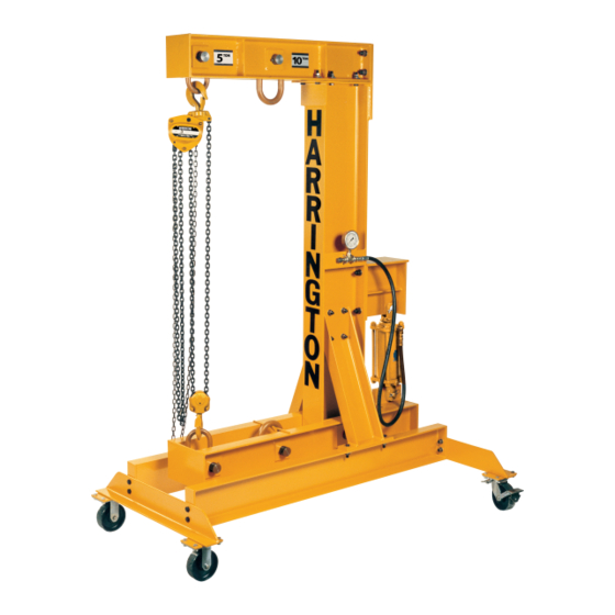
(3) Calibration based on using Harrington 5T Electric Chain Hoist (either NER050L or ER050L).
I
NSTRUCTIONS
1. Collect Calibration Data
(a) Assemble 5 Ton Electric Chain Hoist and properly calibrated Force Measuring Device (Load
Cell or Dynamometer) to the 5 Ton link in the test stand (see Fig. 1).
(b) Connect power to test stand control panel.
(c) Connect pendant to test stand control panel.
(d) Connect cable between test stand control panel and hoist.
(e) Connect power to the hoist.
(f) Ensure the Accumulator Discharge Valve located between the accumulator and the reservoir
is closed (handle is perpendicular to the hoses).
(g) Press the On/Off pushbutton on the test stand control panel to turn on the DHLT. The DHLT
pump should begin operating and maintain system pressure between approx 1700-2300 psi.
For DHLT units shipped after 10/2010, the pump should begin operating and maintaining
system pressure between approx. 1700 – 2450 psi.
(h) Turn on the Dynamometer; assure that it is freely suspended from the Test Hoist with no
tension on it (other than the weight of the attached lower shackle). Press its zeroing button
and ensure the read-out indicates zero load.
Note: Do not press the zeroing button any time after testing starts.
(i) Use the Test Hoist to level the lower beam assembly; this minimizes any effects associated
with slant-lifting.
(j) Follow the calibration procedure for both the 5 ton and 10 ton links as follows. Using the
Pressure Control Valve (PCV), slowly adjust the cylinder pressure to increase the system
pressure. An increase of system pressure can be verified by the Cylinder Pressure Gauge
(CPG). See the last page of this document for a data recording chart.
Note: Small movements in the PCV correspond to large changes in the Dynamometer
reading, particularly on the 10 Ton link; avoid large or rapid adjustments to the PCV as
these can lead to pressure oscillations.
Note: During the following procedure, if you go above the target cylinder pressure while
adjusting "up", reduce the cylinder pressure back down below the target value, and then
raise it up to the target value again. Similarly, if you go below the target cylinder
pressure while adjusting "down", raise the cylinder pressure back above the target value,
and then lower it down to the target value again.
H
H
, I
. C
ARRINGTON
OISTS
NC
ONFIDENTIAL
Dynamic Hoist Load Tester (DHLT)
1 of 4
Calibration Procedure
General Use
EDOC0430
Rev. 01 10-5-2016
Advertisement
Table of Contents

Summary of Contents for KITO Harrington DHLT
- Page 1 Dynamic Hoist Load Tester (DHLT) Calibration Procedure URPOSE To provide instructions for calibration of the DHLT. COPE (1) Includes the DHLT. Excludes the SHLT (Static Hoist Load Tester). (2) Includes only calibration. Excludes setting the Pressure Switch and setting the Limit Switch. (3) Calibration based on using Harrington 5T Electric Chain Hoist (either NER050L or ER050L).
- Page 2 Dynamic Hoist Load Tester (DHLT) Calibration Procedure a. 5 Ton link: i. Adjust cylinder pressure up to 200 psi and record dynamometer reading. ii. Adjust cylinder pressure up from 200 psi to 1300 psi in 100 psi increments recording the dynamometer reading at each increment. iii.
- Page 3 Dynamic Hoist Load Tester (DHLT) Calibration Procedure (c) Confirm that the two lines generated on the graph are linear, or close to linear (they will be linear if their R values are very close to 1). If not, investigate the cause, correct, and obtain new test data.
- Page 4 Dynamic Hoist Load Tester (DHLT) Calibration Procedure DHLT CALIBRATION DATA SHEET Date: ____________________________ Serial Number: ______________________________ Force (lbs) Measured by Load Cell Cylinder 5 Ton Link 10 Ton Link Pressure (psi) Down Average Down Average 1,000 1,100 1,200 1,300 General Use EDOC0430 4 of 4 Rev.
Need help?
Do you have a question about the Harrington DHLT and is the answer not in the manual?
Questions and answers