
Subscribe to Our Youtube Channel
Related Manuals for Microbit AS-1269

Summary of Contents for Microbit AS-1269
- Page 1 USER MANUAL AS-1269 AS-1269 Remote controlled Antenna switch Microbit 2.0 AB 2010. All rights reserved Ba-AS1269-PA4 .docx Rev. PA4 – 2017 Okt 17 User manual 1 of 51...
-
Page 2: Table Of Contents
AS-1269 Table of contents Statement of Conditions ................4 General Description ..................5 Step by step AS-1269 setup ................ 6 Hardware ....................8 Bottom ......................8 Top ( under the top cover) ................9 Configuration with Microbit Setup Manager ..........12 FW/HW ....................... - Page 3 AS-1269 FCC Statement .................... 50 Safety Notice ....................50 Disclaimer ....................51 FCC / CE - Declaration of conformity............... 51 Microbit 2.0 AB 2010. All rights reserved Ba-AS1269-PA4 .docx Rev. PA4 – 2017 Okt 17 User manual 3 of 51...
-
Page 4: Statement Of Conditions
2.0 AB reserves the right to make changes to the product described in this document without notice. Microbit does not assume any liability that may occur due to the use or application of the product(s) or circuit layout(s) described herein. -
Page 5: General Description
100m from the schack. The switch is built in stainless steel and can be placed outdoor. It’s normally delivered with SO-239 connectors, but can be ordered with N-connectors, both with PTFE dielectric. Microbit 2.0 AB 2010. All rights reserved Ba-AS1269-PA4 .docx Rev. -
Page 6: Step By Step As-1269 Setup
PC. Follow the instructions about how to install the Microbit Setup Manager (see chapter Configuration with Microbit Setup Manager). 7. Find out how your network is configured and configure the AS-1269 to fit into your network (see chapter Initial IP Setup) with the Microbit Setup Manager. - Page 7 :port number after the dyndns address if you have changed the webserver port from 80 for example http://sm2oan.mine.nu:8000. Enjoy the remote controlling. Microbit 2.0 AB 2010. All rights reserved Ba-AS1269-PA4 .docx Rev. PA4 – 2017 Okt 17...
-
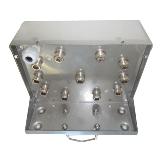
Page 8: Hardware
On the bottom side the antenna connectors are located according to the pictures above. The antenna switch is normally delivered with SO-239 jack but can also be ordered with N connectors. The ventilator will prevent moisture to build up in the housing. Microbit 2.0 AB 2010. All rights reserved Ba-AS1269-PA4 .docx Rev. -
Page 9: Top ( Under The Top Cover)
1. Via the 2.1/5.5 DC jack on the 1216H pcb (see picture). In this case the JMP should be in the Ext Pwr position. 12V DC Microbit 2.0 AB 2010. All rights reserved Ba-AS1269-PA4 .docx Rev. PA4 – 2017 Okt 17... - Page 10 The USB-interface is used to initially set up the IP parameters. It can also be used for downloading new software (can also be done via the WEB-interface). A USB-cable is included with the product. ETHERNET Microbit 2.0 AB 2010. All rights reserved Ba-AS1269-PA4 .docx Rev. PA4 – 2017 Okt 17...
- Page 11 A yellow LED besides the Ethernet connector on the 1216H pcb indicates the status of the Ethernet interface Yellow LED indicates link OK, flashing LED indicates traffic Microbit 2.0 AB 2010. All rights reserved Ba-AS1269-PA4 .docx Rev. PA4 – 2017 Okt 17...
-
Page 12: Configuration With Microbit Setup Manager
Windows version where Netframework 2.0 is not installed, the installer will guide you through the installation of Netframework. When you have finished the installation a new shortcut to Microbit Setup Manager will show up on the desktop. Click on the icon to start Microbit Setup Manager Connect your AS1269 to 12V and connect the USB-cable between your computer and the USB jack on the 1216H pcb. -
Page 13: Fw/Hw
If there is a newer firmware available download it to your desktop, unzip it. Change to the "FW-update" tab. Microbit 2.0 AB 2010. All rights reserved Ba-AS1269-PA4 .docx Rev. PA4 – 2017 Okt 17... -
Page 14: Fw Update
After about a 1 minute the update is finished and the Antenna Switch will restart. When the text "RC-connected" shows up again in the lower field of the Microbit Setup Manager, you can change to the "FW/HW" tab and check software version. -
Page 15: Setup
SWITCHwill restart again and when the text "1216-connected" shows up again in the lower field of the Setup-Manager, you can click on the "Setup" button again to verify the changes. Microbit 2.0 AB 2010. All rights reserved Ba-AS1269-PA4 .docx Rev. -
Page 16: Net Info
USER MANUAL AS-1269 Net info Click on the “Get” button to read the IP setting currently in use by the Switch. Microbit 2.0 AB 2010. All rights reserved Ba-AS1269-PA4 .docx Rev. PA4 – 2017 Okt 17 User manual... -
Page 17: Initial Ip Setup
The default Ip settings from the factory is 192.168.0.236. The net mask is 255.255.255.0, gateway and DNS is 192.168.0.1. To be able to contact the AS-1269 via the network you must configure the units to fit into your home network. You can check your network configuration from your PC. - Page 18 In this case all the default IP setting will be OK. (*) In most cases the Gateway and the DNS server is the same and the IP of the router. Microbit 2.0 AB 2010. All rights reserved Ba-AS1269-PA4 .docx Rev.
- Page 19 AS-1269 In another network, this is the result of the ipconfig command. Your PC IP address in this example is 192.168.128.10 this means that the IP of the AS-1269 must have IP:s in the area 192.168.128.2 to 192.168.128.255. The Netmask is 255.255.128.0 this the Netmask in the ANTENNA SWITCHshould be the same The Default gateway is 192.168.128.1 the Gateway in the AS-1269 should be the same...
- Page 20 USER MANUAL AS-1269 Microbit 2.0 AB 2010. All rights reserved Ba-AS1269-PA4 .docx Rev. PA4 – 2017 Okt 17 User manual 20 of 51...
-
Page 21: Configuration With Web-Interface
AS-1269 Configuration with WEB-interface Before you can use your Antenna switch AS-1269 you must configure it. The unit will have the default IP addresses 192.168.0.236. The net mask is 255.255.255.0. The configuration is easiest done via the web interface. Be aware of that your PC must be in the same net e.g. - Page 22 USER MANUAL AS-1269 The info page shows some static information about the Antenna switch as firmware revision etc. and also the basic IP-configuration. Microbit 2.0 AB 2010. All rights reserved Ba-AS1269-PA4 .docx Rev. PA4 – 2017 Okt 17 User manual...
-
Page 23: Set Antennas
Inputs If you have connected the input to some sensor, you can se the status of the two inputs on this page. High is indicating a open input. Microbit 2.0 AB 2010. All rights reserved Ba-AS1269-PA4 .docx Rev. PA4 – 2017 Okt 17... -
Page 24: Temperature/Rh
Temperature/RH A 1-wire temp or/and humidity sensor can be connected to Bus B, If it’s connected you can see the readings on this page Microbit 2.0 AB 2010. All rights reserved Ba-AS1269-PA4 .docx Rev. PA4 – 2017 Okt 17... - Page 25 USER MANUAL AS-1269 Microbit 2.0 AB 2010. All rights reserved Ba-AS1269-PA4 .docx Rev. PA4 – 2017 Okt 17 User manual 25 of 51...
-
Page 26: Ip Settings
The IP Settings menu is used to setup the initial IP parameters needed for the unit to connect to the IP network. Down below the settings are described more in details. Microbit 2.0 AB 2010. All rights reserved Ba-AS1269-PA4 .docx... - Page 27 100 Mbit LAN (*) If you use fixed settings you must have a managed switch where you can set the same setting. Microbit 2.0 AB 2010. All rights reserved Ba-AS1269-PA4 .docx Rev. PA4 – 2017 Okt 17...
- Page 28 “empty” (default) “username” Web page pwd Password for the web pages and telnet connection. “empty” (default) “password” Microbit 2.0 AB 2010. All rights reserved Ba-AS1269-PA4 .docx Rev. PA4 – 2017 Okt 17 User manual 28 of 51...
-
Page 29: Antenna Settings
Antenna settings At the Antenna settings page you can enter a text string which describe the antenna you have connected to the antenna ports. Microbit 2.0 AB 2010. All rights reserved Ba-AS1269-PA4 .docx Rev. PA4 – 2017 Okt 17... -
Page 30: Serial Settings
P1. The serial parameters are set on the Serial page. This settings has no effect when you have connected the Antenna switch to the RRC over IP Microbit 2.0 AB 2010. All rights reserved Ba-AS1269-PA4 .docx... -
Page 31: Advanced Settings
You can select some modes which only listen and do not send any questions. Elecraft K3 uses the Yeasu settings. This setting are used both for control via the serial port and over IP. Microbit 2.0 AB 2010. All rights reserved Ba-AS1269-PA4 .docx Rev. - Page 32 Address sets the CI-V address of the antenna switch it self. If you have more than one equipment which is a “controller” you may have to change the address to a different one. Microbit 2.0 AB 2010. All rights reserved Ba-AS1269-PA4 .docx...
-
Page 33: Dynamic Dns Setting
The Antenna Switch has a Dynamic DNS client to be used when the Internet Service Provider (ISP) uses dynamic IP addresses instead of fixed IP address. The AS-1269 supports our own free Remoterig dynamic DNS service and DynDNS which is not free for new users anymore. -
Page 34: Remoterig Dynamic Dns Service
After that click on “Submit” and “Apply changes”, the AS-1269 will restart. After the switch has restarted go back to the Dynamic DNS settings page. You will now see that the settings Own hostname, Username and Password are automatically generated. - Page 35 Remember that DNS address like this is only for use when you connect over the internet, as long as you are operating on you own LAN use the IP address. Microbit 2.0 AB 2010. All rights reserved Ba-AS1269-PA4 .docx Rev.
-
Page 36: Dyndns Dynamic Dnsservice
QTH changes. You need to register an account at http://www.dyndns.com/services/dns/dyndns/ and get a domain name. There are other providers of the same service but AS-1269 only supports DynDNS or Remoterig ddns. Microbit 2.0 AB 2010. All rights reserved Ba-AS1269-PA4 .docx... - Page 37 Own host name Domain name registered at DynDNS.com. Example: my-radio-site.ham-radio-op.net Username Dynamic DNS account username. Password Dynamic DNS account password. Microbit 2.0 AB 2010. All rights reserved Ba-AS1269-PA4 .docx Rev. PA4 – 2017 Okt 17 User manual 37 of 51...
-
Page 38: Ping Settings
If you use this function, be sure that the IP-address you have chosen to ping is a IP-address which is always reachable. Microbit 2.0 AB 2010. All rights reserved Ba-AS1269-PA4 .docx Rev. - Page 39 If Test mode is activated it can be set to 10-65535 Failure count to reboot Sets how many times the ping is allowed to fail before reboot is done. (1-255, default 3 ) Microbit 2.0 AB 2010. All rights reserved Ba-AS1269-PA4 .docx Rev. PA4 – 2017 Okt 17...
-
Page 40: Radio Rrc Settings
Antenna switch to talk to the radio via the RRC. Note the RRC must be connected to the radio CAT port via COM2 if it should work. Ip number and port should match the settings in the Radio-RRC. Microbit 2.0 AB 2010. All rights reserved Ba-AS1269-PA4 .docx Rev. -
Page 41: Antenna Selection
First select which antennas you want to be automatically selected on the bottom line. Then you can enter the frequency ranges in the boxes to the left, ant mark which antenna port you want to be active for each range. Microbit 2.0 AB 2010. All rights reserved Ba-AS1269-PA4 .docx Rev. - Page 42 If you want the antennas to be deselected eg. grounded, after a while when the radio is switched off and the switch get no answers on frequency requests, you can set a “Disconnect timeout. Microbit 2.0 AB 2010. All rights reserved Ba-AS1269-PA4 .docx Rev.
-
Page 43: Application Firmware Upgrade
RC. When the firmware is updated the Antenna Switch restart. Note -- Do not interrupt the upgrade process in any way. Microbit 2.0 AB 2010. All rights reserved Ba-AS1269-PA4 .docx... -
Page 44: Bootloader Firmware Upgrade
Restart device Restart device can be used if you want to reset and restart the Antenna Switch without saving any changes (before apply changes) or just for ordinary reset. Microbit 2.0 AB 2010. All rights reserved Ba-AS1269-PA4 .docx Rev. PA4 – 2017 Okt 17... -
Page 45: Networks And Firewalls
Antenna Switch. The following default IP ports are used (changeable) port number function WEB interface WEB interface are TCP-based. Microbit 2.0 AB 2010. All rights reserved Ba-AS1269-PA4 .docx Rev. PA4 – 2017 Okt 17 User manual 45 of 51... -
Page 46: Portforwarding
There is one row assigned for each port (service) all refereeing to the IP of the Radio-RRC and the AS-1269 at the 5 row. Microbit 2.0 AB 2010. All rights reserved Ba-AS1269-PA4 .docx Rev. PA4 – 2017 Okt 17... -
Page 47: Appendix D - Manual Antenna Switch
There is a extra ground connection also marked GND. Note that the Antenna port numbering is different from the picture shown on page 8 Microbit 2.0 AB 2010. All rights reserved Ba-AS1269-PA4 .docx Rev. PA4 – 2017 Okt 17... - Page 48 USER MANUAL AS-1269 Microbit 2.0 AB 2010. All rights reserved Ba-AS1269-PA4 .docx Rev. PA4 – 2017 Okt 17 User manual 48 of 51...
-
Page 49: Appendix E - Technical Data
(*1) All unused antenna outputs are grounded, The RF card control lines are surge protected with Metal Oxide Varistors (*2) The control cable should be shielded (FTP) CAT-5e or better. Microbit 2.0 AB 2010. All rights reserved Ba-AS1269-PA4 .docx Rev. -
Page 50: Appendix F - Safety And Regulatory Information
Never connect a power supply of more than 18 VDC to the power jack. The supply voltage must be between 10 V and 18 V. to prevent damaging the device. Microbit 2.0 AB 2010. All rights reserved Ba-AS1269-PA4 .docx Rev. - Page 51 The author has written this document to the best of his knowledge, but does not guarantee that the contents will satisfy the desire and expectation of the reader. The author or Microbit takes no responsibility for damage or injuries of any kind that may arise from the use and miss use of the product or information contained.
Need help?
Do you have a question about the AS-1269 and is the answer not in the manual?
Questions and answers