Table of Contents
Advertisement
Advertisement
Table of Contents

Related Manuals for Dobot M1 Pro

Summary of Contents for Dobot M1 Pro
- Page 1 User Guide M1 Pro Hardware User Guide Issue: V1.1 Date: 2021-07-08 DISTRIBUTOR : iMS Motion Solution (Johor) Sdn. Bhd. y Co., Ltd ® TEL : +607-8635240 FAX : +607-8637240 Mobile : +6019-6774477 Email : info@ims.com.my HOTLINE : 1700-818-330 www.ims.com.my...
- Page 2 Even if follow this document or any other related instructions, Damages or losses will be happening in the using process, Dobot shall not be considered as a guarantee regarding all security information contained in this document.
- Page 3 Dobot M1 Pro Hardware User Guide Preface Purpose This Document describes the functions, technical specifications, installation guide of Dobot M1 Pro robot, making it easy for users to fully understand and use it. Intended Audience This document is intended for: ...
-
Page 4: Table Of Contents
Dobot M1 Pro Hardware User Guide Contents Security Precautions ....................1 Security Warning Sign ...................... 1 General Security........................ 1 Personal Security ......................4 Overview ........................6 Technical Specifications ....................7 Robot Dimension ......................8 M1 Pro Dimension ....................8 End-effector Dimension ..................8 Robot Workspace ...................... -
Page 5: Security Precautions
Dobot M1 PRO Hardware User Guide Security Precautions This topic describes the security precautions that should be noticed when using this product. Please read this document carefully before using the robot for the first time. This product needs to be carried out in an environment meeting design specification. You cannot remold the product without authorization, otherwise, it could lead to product failure, and even personal injury, electric shock, fire, etc. - Page 6 Dobot M1 PRO Hardware User Guide circuit, otherwise, it is vulnerable to injury the device or the person. You should comply with the local laws and regulations when operating the robot. The security precautions in this document are only supplemental to the local laws and regulations.
- Page 7 Dobot M1 PRO Hardware User Guide When the robot is transported, the packaging needs to be fixed to ensure that the robot is stable. After removing the outer packaging, please make sure that the robot maintains the original packing posture and the brakes on each axis are normal.
-
Page 8: Personal Security
Dobot M1 PRO Hardware User Guide RF source without shielding, otherwise, it could lead to robot abnormally. When the operator commissioning or operates the equipment, it shall be done in the safe space of the equipment. WARNING In order to protect the equipment and personal safety, when turning off the power, please press the switch, then unplug the AC power cable. - Page 9 Dobot M1 PRO Hardware User Guide Do not touch the terminal blocks or remove the interval circuit components in 10 minutes after the power is shut off, to avoid an electric shock since there is residual capacitance inside the robot.
-
Page 10: Overview
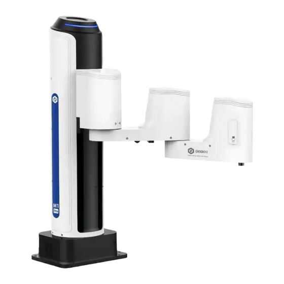
Overview Dobot Master 2 generation robotic arm (Dobot M1 Pro for short) focuses on the light industrial market with great potential, and supports teaching, playback, script control, blockly, vision identity and other functions, which is flexibly used in intelligent sorting, circuit board... -
Page 11: Technical Specifications
Dobot M1 PRO Hardware User Guide Technical Specifications Table 2.1 M1 Pro technical parameters Product DOBOT M1 Pro Model DT-M1-P4R15-01I Weight 15.7kg Max load 1.5kg Reach 400mm Power supply 100~240 VAC,50/60Hz Rated voltage DC48V Installation Table installation, indoor Rated power 192W ±0.02mm... -
Page 12: Robot Dimension
Immunity standard for industrial environments EN 61000-6-4:2019 Electromagnetic compatibility (EMC). Generic standards. Emission standard for industrial environments Robot Dimension M1 Pro Dimension Figure 2.2 shows the dimension of M1 Pro robot. Figure 2.2 M1 Pro dimension End-effector Dimension Issue V1.1 (2021-07-08) User Guide... -
Page 13: Robot Workspace
Dobot M1 PRO Hardware User Guide You can install the matching gripper, suction cup on the end of the M1 Pro for transporting and intelligent sorting. Figure 2.3 shows the dimension of end-effector. Figure 2.3 End-effector dimension Robot Workspace Figure 2.4 shows the workspace of M1 Pro robot. -
Page 14: End Flange Size
Dobot M1 PRO Hardware User Guide When operating the robot, be sure to operate inside the workspace. End Flange Size Figure 2.5 End flange size Stop Time and Angle The Max. stop time and angle of axis J1, J2, J3 and J4 at the max speed, load and arm stretch are shown below. -
Page 15: Product Features
Pro can move to nearly any position and orientation within a given work envelope. You need to specify the arm orientation when M1 Pro is moving. If you fail to do so, M1 Pro may move following an unexpected path, resulting in interference with peripheral equipment. The arm orientations are shown in Figure 2.7 and Figure 2.8. -
Page 16: Coordinate System
Coordinate System 2.8.2.1 Joint Coordinate System The Joint coordinate system is determined by the motion joints. Figure 2.9 shows the Joint coordinate system of a M1 Pro robot. All the joints are rotating joints. M1 Pro contains four joints. ... - Page 17 J3 is the moving joint, which is used for the movement of the end effector in the perpendicular plane. The positive direction of J3 is vertical upward. Figure 2.9 Joint coordinate of a M1 Pro robot 2.8.2.2 Base Coordinate System The Base coordinate system is determined by the base.
- Page 18 Dobot M1 PRO Hardware User Guide Figure 2.10 Base coordinate system of M1 Pro robot 2.8.2.3 Tool Coordinate System Tool coordinate system is the coordinate system that defines the distance and rotation angle of the offset, of which the origin and orientations vary with the position and attitude of the workpiece located at the robot flange.
- Page 19 Dobot M1 PRO Hardware User Guide Figure 2.11 The default Tool coordinate system of M1 Pro robot 2.8.2.4 User Coordinate System The User coordinate system is a movable coordinate system which is used for representing equipment like fixtures, workbenches. The origin and the orientations of axes can be defined based on site requirements, to measure point data within the workspace and arrange tasks conveniently.
-
Page 20: Electrical Specifications
Dobot M1 PRO Hardware User Guide Electrical Specifications Interface of Base External Interface Board Description Figure 3.1 shows the interface board of the Base. Table 3.1 lists the description. Figure 3.1 Interface board of the base Table 3.1 Interface description... -
Page 21: Digital Input
Dobot M1 PRO Hardware User Guide screen printing Description I/O interface interface of the M1 Pro is shown in Figure 3.2,Table 3.2 lists the description of Encoder interface. Encoder Figure 3.2 Encoder interface Table 3.2 Encoder Interface description Description ABZ_A+... -
Page 22: Digital Output
Dobot M1 PRO Hardware User Guide Figure 3.4 Simple digital input circuit Table 3.3 Technical specifications Item Specification Input channel 16 channels Connection method Europe type terminal Input type Input voltage (DC) 24V± 10% Isolation method Optical coupling isolation Digital Output Figure 3.5 shows the simple digital output circuit and Table 3.4 lists the technical... -
Page 23: End-Effector I/O Interface Description
Magnetic isolation End-effector I/O Interface Description The end-effector I/O interfaces of the M1 Pro include a RS485 interface, 4 digital inputs and 4 digital outputs, as shown in Figure 3.6, Table 3.5 lists the description of End-effector I/O interface. Figure 3.6 End-effector I/O interface Table 3.5 End-effector I/O interface description... -
Page 24: Installation
Dobot M1 PRO Hardware User Guide Installation Installation Environment To maintain the controller and robot performance and to ensure the safety, please place them in an environment with the following conditions. Install indoors with good ventilation. Keep away from excessive and shock. -
Page 25: Maintenance And Repair
Remove all parts that do not belong to Dobot. Before returning to Dobot, please make a backup copy of the files. Dobot will not be responsible for the loss of programs, data or files stored in robot. ... - Page 26 Dobot technical engineer. In addition, overhauls are required every 10,000 hours of operation time or every 3 years. If you are not clear about the maintenance processes, please contact Dobot technical engineer. Issue V1.1 (2021-07-08) User Guide...
Need help?
Do you have a question about the M1 Pro and is the answer not in the manual?
Questions and answers