
Subscribe to Our Youtube Channel
Related Manuals for Sub-Zero WOLF MS24-1100


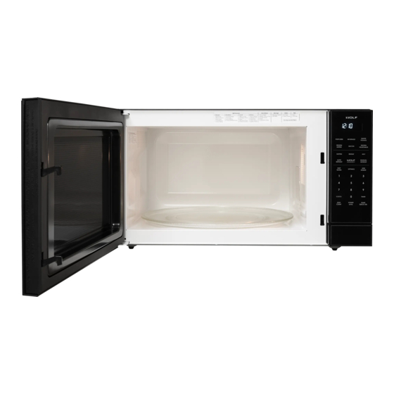
Summary of Contents for Sub-Zero WOLF MS24-1100
-
Page 1: General Table Of Contents
subzero.com 800.222.7820 MS24-1100 Service Manual General Information Troubleshooting Guide Component Access & Removal Wiring Diagrams... -
Page 2: Precautions To Be Observed Before And During Servicing
MS24-1100 PRECAUTIONS TO BE OBSERVED BEFORE AND DURING SERVICING TO AVOID POSSIBLE EXPOSURE TO EXCESSIVE MICROWAVE ENERGY (a) Do not operate or allow the oven to be operated with the door open. (b) Make the following safety checks on all ovens to be serviced before activating the magnetron or other microwave source, and make repairs as necessary: (1) interlock operation, (2) proper door closing, (3) seal and sealing surfaces (arcing, wear, and other damage), (4) damage to or loosening of hinges and latches, (5) evidence of dropping or abuse. -
Page 3: Warning To Service Personnel
MS24-1100 WARNING TO SERVICE PERSONNEL Microwave ovens contain circuitry capable of pro- ducing very high voltage and current, contact with following parts may result in a severe, possibly fatal, electrical shock. (Example) High Voltage Capacitor, High Voltage Power Transformer, Magnetron, High Voltage Rectifier Assembly, High Voltage Harness etc.. -
Page 4: Microwave Measurement Procedure
MS24-1100 MICROWAVE MEASUREMENT PROCEDURE A. Requirements: 1) Microwave leakage limit (Power density limit): The power density of microwave radiation emitted by a microwave oven should not exceed 1mW/cm at any point 5cm or more from the external surface of the oven, measured prior to acquisition by a purchaser, and thereafter (through the useful life of the oven), 5 mW/cm at any point 5cm or more from the external surface of the oven. -
Page 5: Foreward
MS24-1100 SERVICE MANUAL MICROWAVE OVEN MS24-1100 FOREWORD This Manual has been prepared to provide WOLF Service Personnel with operation and service information for the WOLF microwave. It is recommended that service personnel carefully study the entire text of this manual so that they will be qualified to render satisfactory customer service. -
Page 6: Specifications
MS24-1100 SPECIFICATION ITEM DESCRIPTION Power Requirements 120 Volts / 13.0 Amperes/1500Watts 60 Hertz Single phase, 3 wire grounded Power Output 1100 watts (IEC-705 TEST PROCEDURE) Operating frequency of 2450MHz Case Dimensions Width 24" Height 13-3/8" Depth 19-1/8" Cooking Cavity Dimensions Width 17-3/8"... - Page 7 MS24-1100 Grounded CAUTION: DO NOT UNDER ANY CIRCUMSTANCES CUT OR Receptacle Box REMOVE THE ROUND GROUNDING PRONG FROM THIS PLUG. 3-Pronged Plug Grounding Pin 3-Pronged Receptacle OVEN DIAGRAM Door seals and Ventilation Menu label Oven light sealing surfaces openings (rear) Power supply cord Rating plate Interactive display...
-
Page 8: Description Of Operating Sequence
MS24-1100 OPERATION DESCRIPTION OF OPERATING SEQUENCE The following is a description of component functions dur- 7. The monitor switch electrically monitors the operation of ing oven operation. the primary and third door switch and is mechanically associated with the door so that it will function in the OFF CONDITION following sequence. -
Page 9: Sensor Cooking Condition
MS24-1100 2. The coil of shut-off relay (RY-1) is energized, the turntable motor are turned on, but the power transformer is not SENSOR COOKING CONDITION turned on. 3. After about 16 seconds, the cook relay (RY-2) is Using the SENSOR function, food is cooked without figur- energized. -
Page 10: Schematics And Troubleshooting Oven Off Schematic Diagram
MS24-1100 SCHEMATIC NOTE: CONDITION OF OVEN 1. DOOR CLOSED 2. CLOCK APPEARS ON DISPLAY THIRD PRIMARY DOOR INTERLOCK CAVITY TEMP SWITCH SWITCH FUSE FUSE N.O. COM. N.O. OVEN TURN TABLE LAMP MOTOR MOTOR POWER TRANSFORMER N.C. DOOR N.O. COM. SENSING MONITOR SWITCH SWITCH... -
Page 11: Description And Function Of Components
DESCRIPTION AND FUNCTION OF COMPONENTS MS24-1100 DOOR OPEN MECHANISM CAUTION: BEFORE REPLACING A BLOWN C/T FUSE TEST THE DOOR SENSING SWITCH, SEC- The door is opened by pushing the open button on the con- ONDARY INTERLOCK RELAY (RY2), RELAY trol panel, refer to the Figure D-1. When the open button is (RY1), PRIMARY/THIRD DOOR INTERLOCK pushed, the open button pushes up the switch lever, and SWITCH AND MONITOR SWITCH FOR PROP-... -
Page 12: Troubleshooting Guide
MS24-1100 TROUBLESHOOTING GUIDE Never touch any part in the circuit with your hand or an uninsulated tool while the power supply is connected. When troubleshooting the microwave oven, it is helpful to follow the Sequence of Operation in performing the checks. Many of the possible causes of trouble will require that a specific test be performed. -
Page 13: Test Procedure Chart
MS24-1100 CK = Check / RE = Replace RE RE A B C D E E F F G H RE RE CK I CK CK CK J K L TEST PROCEDURE POSSIBLE CAUSE DEFECTIVE PARTS PROBLEM CONDITION Home fuse or circuit breaker blows when power cord is plugged into wall receptacle Monitor fuse blows when power... -
Page 14: Magnetron Assembly Test
MS24-1100 TEST PROCEDURES PROCEDURE COMPONENT TEST LETTER MAGNETRON ASSEMBLY TEST 1. Disconnect the power supply cord, and then remove outer case. 2. Open the door and block it open. 3. Discharge high voltage capacitor. 4. To test for an open filament, isolate the magnetron from the high voltage circuit. A continuity check across the magnetron filament leads should indicate less than 1 ohm. -
Page 15: High Voltage Rectifier Test
MS24-1100 TEST PROCEDURES PROCEDURE COMPONENT TEST LETTER HIGH VOLTAGE RECTIFIER TEST 1. Disconnect the power supply cord, and then remove outer case. 2. Open the door and block it open. 3. Discharge high voltage capacitor. 4. Isolate the rectifier from the circuit. Using the highest ohm scale of the meter, read the resistance across the terminals and observe, reverse the leads to the rectifier terminals and observe meter reading. -
Page 16: Primary And Third Door Switch Test
MS24-1100 TEST PROCEDURES PROCEDURE COMPONENT TEST LETTER 5. If the C/T fuse is blown when the door is opened, check the secondary interlock relay, primary interlock switch and monitor switch according to the "TEST PROCEDURE" for those switches before replacing the blown monitor fuse. CAUTION: BEFORE REPLACING A BLOWN C/T FUSE, TEST THE SECONDARY INTERLOCK RELAY, PRIMARY INTERLOCK SWITCH, DOOR SENSING SWITCH AND MONITOR SWITCH FOR PROPER OPERATION. -
Page 17: Blown Monitor Fuse Test
MS24-1100 TEST PROCEDURES PROCEDURE COMPONENT TEST LETTER 3. Discharge high voltage capacitor. 4. Before performing this test, make sure that the primary switch is operating properly, according to the above Switch Test Procedure. Disconnect the wire lead from the monitor switch (COM) terminal. Check the monitor switch operation by using the ohmmeter as follows. - Page 18 MS24-1100 TEST PROCEDURES PROCEDURE COMPONENT TEST LETTER 2-2 In connection with indicators a) At a certain digit, all or some segments do not light up. b) At a certain digit, brightness is low. c) Only one indicator does not light. d) The corresponding segments of all digits do not light up;...
-
Page 19: Relay Test
MS24-1100 TEST PROCEDURES PROCEDURE COMPONENT TEST LETTER RELAY TEST Disconnect the power supply cord, and then remove outer case. 2. Open the door and block it open. 3. Discharge high voltage capacitor. 4. Disconnect the leads to the primary of the power transformer. 5. -
Page 20: Ah Sensor Test
MS24-1100 TEST PROCEDURES PROCEDURE COMPONENT TEST LETTER AH SENSOR TEST Checking the initial sensor cooking condition Warning: The oven should be fully assembled before following procedure. 1) The oven should be plugged in at least two minutes before sensor cooking. 2) Room temperature should not exceed 95 F(35 3) The unit should not be installed in any area where heat and steam are generated. -
Page 21: Checking Control Unit
MS24-1100 TEST PROCEDURES PROCEDURE COMPONENT TEST LETTER CHECKING CONTROL UNIT (1) Disconnect the power supply cord, and then remove outer case. (2) Open the door and block it open. (3) Discharge high voltage capacitor. (4) Disconnect the sensor connector that is mounted to control panel. (5) Then connect the dummy resistor circuit (see fig.) to the sensor connector of control panel. -
Page 22: Noise Filter Test
MS24-1100 TEST PROCEDURES PROCEDURE COMPONENT TEST LETTER NOISE FILTER TEST 1. Disconnect the power supply cord, and then remove outer case. 2. Open the door and block it open. 3. Discharge high voltage capacitor. 4. Disconnect the leads to the primary of the power transformer. 5. -
Page 23: Absolute Humidity Sensor Circuit
MS24-1100 ABSOLUTE HUMIDITY SENSOR CIRCUIT (1) Structure of Absolute Humidity Sensor With this voltage given, the switches SW1 to SW5 in The absolute humidity sensor includes two thermistors the LSI are turned on in such a way as to change the as shown in the illustration. -
Page 24: Component Replacement And Adjustment Procedures
MS24-1100 COMPONENT REPLACEMENT AND ADJUSTMENT PROCEDURE WARNING AGAINST HIGH VOLTAGE: Microwave ovens contain circuitry capable of producing very high voltage and current, contact with following parts may result in severe, possibly fatal, electric shock. (Example) High Voltage Capacitor, Power Transformer, Magnetron, High Voltage Rectifier Assembly, High Voltage Harness etc.. -
Page 25: Table Of Contents
General Information MS24-1100 MS24-1100 TABLE OF CONTENTS General Table of Contents ..............................1 Precautions to be observed before and during Servicing ..................2 Before Servicing ..............................2 Warning to Service Personnel ..........................3 Microwave Measurement Procedure ........................4 Foreward .................................. 5 Specifications ................................ -
Page 26: Oven Lamp And Lamp Socket Removal
MS24-1100 OVEN LAMP AND LAMP SOCKET REMOVAL 1. Disconnect the power supply cord and remove outer case. 2. Open the door and block it open. 3. Discharge high voltage capacitor. Terminal Oven lamp 4. Pull the wire leads from the oven lamp socket. socket 5. -
Page 27: Cooling Fan Motor Removal
MS24-1100 COOLING FAN MOTOR REMOVAL REMOVAL CAUTION: 1. Disconnect the power supply cord and then remove outer * Do not reuse the removed fan blade because the case. hole (for shaft) may be larger than normal. 2. Open the door and block it open. 3. -
Page 28: Door Sensing Switch/Primary Switch/Third Switch And Monitor Switch Adjustment
MS24-1100 and check continuity of the monitor circuit. Refer to chapter 3. Secure latch hook (with two (2) mounting screws) to oven flange. "Test Procedure" and Adjustment procedure. 4. Make sure that the monitor switch is operating properly DOOR SENSING SWITCH/PRIMARY SWITCH/THIRD DOOR SWITCH AND MONITOR SWITCH ADJUSTMENT 1. - Page 29 MS24-1100 SEALER FILM 6. Re-install choke cover to door panel by pushing. Installation Note: After any service to the door; 1. Put the adhesive tape on the backing film of the sealer (A) Make sure that door sensing switch and secondary film as shown in Fig.
-
Page 30: Wiring Diagram - Pictorial
MS24-1100...
Need help?
Do you have a question about the WOLF MS24-1100 and is the answer not in the manual?
Questions and answers