
Summary of Contents for Thies CLIMA Winddisplay LED
- Page 1 Winddisplay LED Instruction for Use 4.3251.0x.001 / 002 / 902 Ship Version V6.6 Dok. No. 021408/04/21 T H E W O R L D O F W E A T H E R D A T A...
- Page 2 Safety Instructions • Before operating with or at the device/product, read through the operating instructions. This manual contains instructions which should be followed on mounting, start-up, and operation. A non-observance might cause: - failure of important functions - endangerment of persons by electrical or mechanical effect - damage to objects •...
-
Page 3: Table Of Contents
Contents Model ..........................5 Use ..........................6 Functions: ........................7 Equipment: ........................ 8 Display ..........................8 „Rel.“ Wind (Relative Wind) ..................9 „True“ Wind ......................10 Course: 180° Wind Display Shifting ................. 11 Operational Characteristics ....................12 Recommended Choice of Location ................14 Installation........................14 Mechanical Assembly .................... - Page 4 Figures Figure 1: Display ........................9 Figure 2: Rear panel 4.3251.0x.001 ..................15 Figure 3: Rear panel 4.3251.0x.x02 ..................15 Figure 4: Example of Connections ..................18 Figure 5: DIP switch ......................23 Figure 6: Operation ......................31 Tables Table 1: Model ........................5 Table 2: Wind Transmitter Connection Table ................16 Table 3: Device parameters ....................34 Table 4: Error message ......................36 ©...
-
Page 5: Model
1 Model Description Order - No. Equipment Operating voltage Wind indicator LED 4.3251.00.001 6 x RS422 230V AC / 24V AC / 12…35V 5 x RS 422 1 x RS 485 - Firmware for Log/Gyro- system Wind indicator LED 4.3251.01.001 6 x RS422 115V AC / 24V AC / 12…35V 5 x RS 422... -
Page 6: Use
2 Use The wind display LED is a modern, data processing measuring and indicating instrument for representation and serial output of the wind direction and wind velocity as „True“ or „Rel.“ value on ships. „True Wind“ is the wind, which can be observed while the ship is standing still. It is calculated on the basis of the received data in reference to the ship’s movement and the measured relative wind. -
Page 7: Functions
• Output of NMEA 0183 telegrams for actuation of external Winddisplay • Im „Master / Slave“ mode, up to 10 further Winddisplay LED’s can be connected over a maximum distance of 1000m. • Flexible power supply for the Wind display with 230VAC or 24VAC / 12 - 35V DC (optional 115VAC). -
Page 8: Equipment
2.2 Equipment: • 4.3251.0x.001 1 x Wind interface for connection of different types of wind transmitters. • 3 x RS422 (1 x RS 485 *) input interfaces. • 3 x RS422 output interfaces. 4.3251.0x002 Same as 4.3251.0x.001 however, additionally: • 2 x Analogue inputs (temperature, rel. -
Page 9: Rel." Wind (Relative Wind)
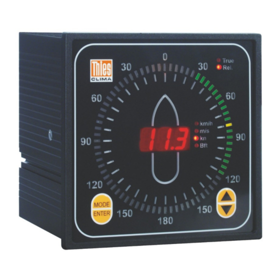
3.1 „Rel.“ Wind (Relative Wind) • Definition refer to chapter 4 Wind velocity (WV): The wind velocity is shown as an instantaneous value on the three-digit red LED display. Units of measurement are m/s, km/h, kn and Beaufort. A red illuminated status status LED shows the selected unit of measurement. -
Page 10: True" Wind
3.2 „True“ Wind • Definition refer to chapter 4 Wind velocity (WV): The wind velocity is indicated as an instantaneous value on the three-digit red LED display. Units of measurement are m/s, km/h, kn and Beaufort. A red illuminated status LED shows the selected unit of measurement. -
Page 11: Course: 180° Wind Display Shifting
3.3 Course: 180° Wind Display Shifting • Forward: With its north marking, the wind direction transmitter resp. the combined wind transmitter is aligned normally to the bow of the ship , which is identical to the symbol on the display (bow = 0°, rear = 180°, course = forward). •... -
Page 12: Operational Characteristics
4 Operational Characteristics Definitions: The „Relative Wind“, the heading and the ship’s speed must be available for calculation of the „True Wind“. The “Relative Wind” is measured by means of a wind transmitter installed on the ship’s bow. Heading and ship’s speed are received via the following NMEA telegrams: NMEA Interface Heading*... - Page 13 The individual calculation steps are as follows: • Break the vectors down into orthogonal components, if necessary. • Subtract the appropriate components, • convert into polar coordinates. The calculation result is the sum of true wind velocity and relative wind direction (TWDS). The true wind direction in reference to north (TWDE) is calculated by adding the heading (HDG): TWDE = TWDS + HDG Approximations...
-
Page 14: Recommended Choice Of Location
The device settings may have to be adjusted prior to installation (refer to chapter 7). 6.1 Mechanical Assembly The Winddisplay LED is designed for switchboard installation. The required switchboard cut- out must measure 138 x 138mm. Two mounting profiles are included in delivery. Upon installation of the device into the switchboard, the mounting profiles are inserted into the rear panel of the casing and screwed into place. -
Page 15: Figure 2: Rear Panel 4.3251.0X.001
COM2 Windsensor TX - Pulse RX - COM3 Down Data TX - Clock Enter Mode RX - Res. Power Supply TX - COM4 230V 0,25AT TX - TX + 115V 0,5 AT RX - RX - RX + TX - COM5 TX - TX +... -
Page 16: Connection Wind Transmitter
6.2.1 Connection Wind Transmitter • For wind transmitter types: Classic, Compact, First-Class (refer to table 2). The wind transmitters are connected to the clamp connector „Wind Sensor“. On connection, it must be observed that pairing of the wind transmitter types (direction and speed) must take place according to chapter 7.2 (Wind Transmitter Type). -
Page 17: Connection Serial Interface Rs422 / Rs485
6.2.2.1 COM 1 and COM 1’ • For wind transmitters with serial data transfer (Ultrasonic- Anemometer 4.38xx.., Wind Direction Transmitter First Class 4.3150.x0.400) and other external Winddisplay LED’s (Slaves). The connection is established via clamp connectors „COM1“ / „COM1’ “. The two clamp connectors of the interface are connected in parallel. -
Page 18: Figure 4: Example Of Connections
Interface configuration RS422 RS485 Rx-/ send send / reception Rx+/ reception The selection of the interface configuration is carried out via the key mode (see 9 „operation“). In the operation mode RS485 the output of the requirement protocol is carried out cyclically for the reception of the VDT-telegram from the ultrasonic. - Page 19 • The cable must at all events be terminated with is characteristic impedance (100Ω to 600Ω according to cable). In the event of several Winddisplay LED’s (Slaves), the resistor must be fitted to the receiver that is the farthest away from the transmitter.
-
Page 20: Connection Analog Inputs
Output cycle (external Winddisplay LED) The telegrams „True Wind“ and „Relative Wind“ are issued every second. With baud rates less than 4800Bd, it may be impossible to terminate output within one second, owing to circumstances. The subsequent telegram is started upon complete output of the previous telegram. -
Page 21: Connection Power Supply
6.2.4 Connection Power Supply • For Winddisplay 4.3251.00. x0x Clamp connector: Clamp connector: Des. Des. AC - Power low voltage Power Protective conductor 24V AC/DC 230V AC 24V AC/DC 230V AC • For Winddisplay 4.3251.01.x0x Clamp connector: Clamp connector: Des. Des. -
Page 22: Connection Sensor Supply Only (With 4.3251.0X.902)
6.2.6 Connection Sensor Supply only (with 4.3251.0x.902) Clamp connector: Des. Vout Vcc1+ 12VDC Vcc2+ 12VDC 6.2.7 Optional Connection (Analogue output) Clamp connector: Des. Output Ch1+ Analogue out Ch2+ Analogue out © Adolf Thies GmbH & Co. KG · Hauptstraße 76 · 37083 Göttingen · Germany 021408/04/21 Phone +49 551 79001-0 ·... -
Page 23: Settings
7 Settings An 8-fold DIP switch (settings) S1…S8 is located on the rear panel of the device (refer to Figure 2: Rear panel 4.3251.0x.001) for basic setting of different parameters. Note: A restart, which is effected via actuation of the key „Info Reset“ or via interruption of the power supply, must be carried out upon change of switch setting. -
Page 24: Setting Wind Transmitter Type
7.2 Setting Wind Transmitter Type The assignment of the wind sensors or wind sensor pairs is carried out using switches S3 and S4 as well as via mode settings (Mode C: for setting see chap. 9). Mode C-0: Wind transmitter Classic or FirstClass Mode C-1: Wind transmitter Compact Wind transmitter type (Wind S4 Mode C... -
Page 25: Setting Wind Reference Nacos (Com 4)
7.3 Setting Wind Reference NACOS (COM 4) Wind reference NACOS 1 2 3 4 6 7 8 Relative (Rel.) wind * True Wind * = Delivery status Setting of the wind reference in the MWV telegram (refer also chap. 8) 7.4 Setting Wind Reference CUSTOMER (COM 5) 1 2 3 4 5 Wind reference CUSTOMER... -
Page 26: Data Protocol
8 Data Protocol The following input/output protocols can be processed Abbreviations: „*“ = identifier for check sum „,“ = separator „H“ = check sum high „L“ = check sum low <STX> = start of text <CR> = carriage return <LF> = line feed COM1 Input (Ultrasonic Anemometer) The COM1 interface is reserved for reception of an ultrasonic anemometer with the following... - Page 27 COM1 and COM1’ Output (External Winddisplay LED) Output of the telegrams for display of Rel./True Wind on the external Winddisplays takes place via COM1. Output of the telegrams „Relative Wind“ [R] and „True Wind“ [T] takes place alternately with an interval of at least 50 ms.
- Page 28 COM2 Input (HDT protocol) : NMEA 0183 V2.0 Receipt of the HDT protocol with the heading contained. In addition, the DDC telegram (see below) can be used to set the brightness in 4 levels. $HEHDT,xx.x,T*HL<CR><LF> T = reference to geographical north heading in degree COM3 Input (VBW, VHW and VTG Protocol) NMEA 0183 V2.0...
- Page 29 COM2 and COM3 input (NMEA DDC): With this telegram the brightness of the display can be adjusted in 4 steps. Note: After receiving a valid DDC telegram, the normal brightness setting via the buttons (Mode0) is blocked. $__DDC,a,,,C*HL<CR><LF> a: display-brightness level D=Daytime (day) K=Dusk (Dusk)
- Page 30 $WIMWV,ddd,R,ss.s,M,A*HL<CR><LF> Status: A=valid data, V=invalid data Unit: m/s Value wind velocity in m/s R = relative wind / T = true wind Value wind direction in degrees The wind reference can be set in the MWV telegram by means of DIP switches 5 and 6 (refer to chapter 7.3 and 7.4).
-
Page 31: Operation
9 Operation The Winddisplay LED is operated from the front by means of 5 buttons, as shown in the diagram below. A short beep acknowledges the actuation of any button. The Winddisplay LED can additionally be operated via the clamp connector „Remote“ located on the rear panel of the device, as well as via external buttons. - Page 32 MODE MODE 0 Adjustment of brightness The brightness of the LED display is dimmed in 18 steps via buttons ▲ & ▼ Adjustment of MAX and MIN brightness: The previously set brightness can respectively be stored as MAX or MIN value via simultaneous actuation of buttons ▲...
- Page 33 MODE 8 Setting the brightness of the 4 levels of the DDC telegram MODE 9 Mode 8: O Backlighting Off Mode 9: D Daytime (Day) MODE A Mode A: K DusK (Dusk) MODE B Mode B: N Nighttime (Night) MODE C Setting the characteristic of the wind transmitter C –...
-
Page 34: Table 3: Device Parameters
An LED test is started by pressing the button INFO & RESET. • All LED’s illuminate • Display of device parameters (refer to table 3) • Restart of the Winddisplay LED. Example Device parameters Display Software Version No. (e.g.) r 1.1... -
Page 35: Functional Test
10 Functional Test The Winddisplay LED carries through some test procedures during a restart or upon actuation of the INFO & RESET button (refer to chapter 9). An error code appears in the display in the event of an error (refer to chapter 11). All wind transmitters must be disconnected in order to be able to perform a complete Windinterface test. -
Page 36: Table 4: Error Message
WT “FF.F” Wind speed error in the telegram (for ex. Ultrasonic). WD “FFF” Wind direction error in the telegram (for ex. Ultrasonic). REL/TRUE error Check transmitted protocol (error „a“ appears twice in telegram). No reception from ultrasonic VDT protocol - check connection (RS485 half-duplex). COM 3 E20 * Timeout, no reception. -
Page 37: Maintenance
A dry, dust-free room with temperatures ranging from –20 ...+50°C is compulsory for storage of the Winddisplay LED. We recommend box storage of the device. Fuse A mains fuse is located on the rear panel of the Winddisplay LED. The fuse holder can be opened with a screwdriver. Attention: Strictly the following fuses may be used in the event of a fault: 230V ;... -
Page 38: Technical Specifications
13 Technical Specifications Description Wind transmitter inputs Wind direction Input Thies Seriell Synchron Type Compact 4.3129.00.000 / 4.3129.60.000 Classic 4.3125.x2.100 / 101 Classic 4.3336.x1.00x / 4.3336.x2.00x First Class 4.3150.x0.000 Sampling rate 10Hz Wind velocity Input Frequency Ua ≤ 1 V , Ua ≥3.3V Level (Ua) Frequency (max) Compact... - Page 39 Temperature ±1.5hPa at constant pressure influence Voltage supply of Only with model 4.3251.0x.902 external sensors Output 2 x Voltage U (Vcc) 12V (is programmed on request). Icc (max) + U1 <110mA Fuse Polyswitch ca. 140mA Operating voltage mains 230V AC ( with 4.3251.00.00x) 115V AC ( with 4.3251.01.00x) Mains fuse 0.25AT resp.
-
Page 40: Dimension Diagram
14 Dimension Diagram Control panel opening as per DIN 43700 x 138 Terminals 2 fixing brackets (left and right) © Adolf Thies GmbH & Co. KG · Hauptstraße 76 · 37083 Göttingen · Germany 021408/04/21 Phone +49 551 79001-0 · Fax +49 551 79001-65 · info@thiesclima.com ·www.thiesclima.com Page 40 of 41... -
Page 41: Ec-Declaration Of Conformity
15 EC-Declaration of Conformity Document-No.: 002003 Month: 04 Year: 21 A D O L F T H I E S G m b H & C o. K G Manufacturer: Hauptstr. 76 D-37083 Göttingen Tel.: (0551) 79001-0 Fax: (0551) 79001-65 email: Info@ThiesClima.com This declaration of conformity is issued under the sole responsibility of the manufacturer... - Page 42 Please contact us for your system requirements. We advise you gladly. ADOLF THIES GMBH & CO. KG Meteorology and environmental metrology Hauptstraße 76 · 37083 Göttingen · Germany Phone +49 551 79001-0 · Fax +49 551 79001-65 info@thiesclima.com www.thiesclima.com © Adolf Thies GmbH & Co. KG · Hauptstraße 76 · 37083 Göttingen · Germany 021408/04/21 Phone +49 551 79001-0 ·...
Need help?
Do you have a question about the Winddisplay LED and is the answer not in the manual?
Questions and answers