
Related Manuals for Motion AXIS STUIFMEEL Thomson PC-Series

Summary of Contents for Motion AXIS STUIFMEEL Thomson PC-Series
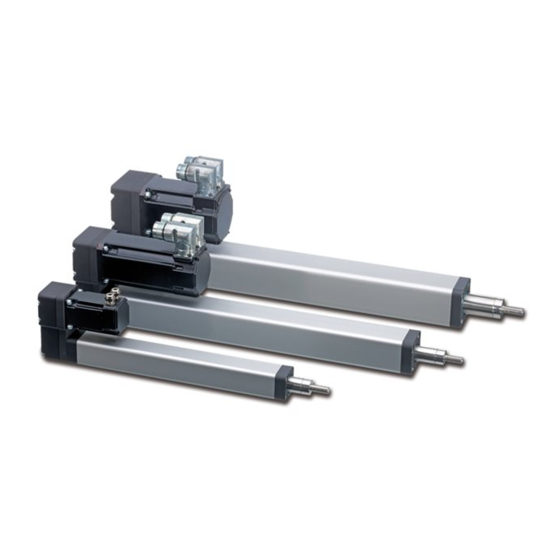
- Page 1 Thomson PC-Series™ Precision Linear Actuator Installation Manual Edition 2014-01 DW110697GB...
- Page 2 Thomson Version History Edition Reason for revision 2014-01 First edition Warranty The Thomson PC-Series™ is warranted to be free from defects in materials and workmanship for a period of twelve (12) months from date of delivery. The application of this product is the responsibility of the buyer and Thomson makes no representation or warranty as to the suitability of the product for any particular use or purpose.
-
Page 3: Table Of Contents
Contents Thomson Contents 1. General ...................... 4 About this manual ....................4 Target group ......................4 Symbols used ....................... 4 Transport and storage ..................4 Disposal ........................ 4 Support ......................... 4 2. Safety 5 Safety notes ......................5 3. Standards ....................5 EC Declaration of conformity ................ -
Page 4: General
Thomson General 1. General 1.1 About this manual This manual decribes how to install the Thomson PC-Series precision linear actuator mechanically and electrically. It also contains, among other things: • technical data • dimensional drawings • type designation key. It is important to carefully read this manual before installing the actuator and to have the correct qualifications needed to perform the installation. -
Page 5: Safety
Safety and Standards Thomson 2. Safety 2.1 Safety notes • Only properly qualified personnel are permitted to perform mechanical and electrical installation, service or maintenance on this product. Properly qualified personnel are familiar with mechanical or electrical installation work and that have the appropiate qualifications for their jobs. •... -
Page 6: Installation
Thomson Installation 4. Installation 4.1 Name plate The name plate can be found on the actuator cover tube. It will tell you which model of actuator you have and its basic performance data. Please study the name plate to see what type of actuator you have before starting any installation or service on the actuator. -
Page 7: Operation Environment
Installation Thomson 4.3 Operation environment Min. -20° C Max. +70° C IP65 Operation temperature range is between -20 to +70° Celcius. Protection degree against the ingress of water and particles is IP65. 4.4 General mounting guidelines The unit can be mounted in any direction but do not mount the actuator so that the cover tube is subjected to any bending or twisting forces. -
Page 8: Mounting Of The Unit Using The Mounting Holes
Thomson 4.5 Mounting of the unit using the mounting holes All PC-Series actuators have mounting holes in the front plate while the parallel style also have mounting holes in the rear plate on the belt gear. The mounting holes can be used to attach the unit to the support or to the mounting accessories designed for the purpose (see point 4.7). -
Page 9: Mounting Of The Unit Using The Extension Tube Rod End
Thomson 4.6 Mounting of the unit using the extension tube rod end The extension tube rod end always have either a male or a female threaded rod end mounted from the factory. A spherical joint (see point 4.7.1) or a clevis (see point 4.7.2) can also be mounted to the male threaded rod end, either from factory or by the customer as a seperate part in which case you must follow the below instructions plus the instructions for the spherical joint or the clevis. -
Page 10: Mounting Of The Unit Using The Mounting Accessories
Thomson 4.7 Mounting of the unit using the mounting accessories The unit can be shipped with mounting accessories mounted from the factory, in this case the designation on the name plate and the ordering key (table T6.2.1) will help you determine which accessory the unit is equipped with and which mounting instruction below to follow. - Page 11 Thomson 4.7.3 Rear clevis - for PC25 parallel style models The rear clevis it mounted to the rear plate of the belt gear housing. All necessary screws to attach it to the actuator is included. Make sure to tighten all four screws according to table T6.3.1.
- Page 12 Thomson 4.7.5 Front mounting plate The front mounting plate it mounted to the front plate of the cover tube. All necessary screws to attach it to the actuator is included. Make sure to tighten all four screws according to table T6.3.1. PC25 6.6 (2×) D607 415...
- Page 13 Thomson 4.7.7 Foot mount for parallel style models The foot mount consists of a front and rear bracket. All necessary screws are to attach it to the actuator is included. Make sure to tighten all attachement screws according to table T6.3.1. PC25 D607 421 PC32...
- Page 14 Thomson 4.7.9 Fixed rear trunnion for parallel style models The fixed rear trunnion consist of a plate with two shafts. All necessary screws are to attach it to the actuator is included. Make sure to tighten all attachement screws according to table T6.3.1.
-
Page 15: Mounting Of Sensor Brackets
Thomson 4.8 Mounting of sensor brackets The bracket can be installed over the left or right corner of the cover tube surface under which the sensor magnet travels. The correct cover tube surface is marked with a magnet sign sticker (1). The bracket (2) is secured using the worm drive clamp (3) that are put around the cover tube and the bracket. - Page 16 Thomson 4.11.1 Motor installation on inline style models with RediMount system 1. Make sure the extension tube is fully retracted and then remove the sealing plug. 2. Press the motor shaft on to the coupling inside of the flange. 3. Bolt the motor to the flange using four screws. Tighten the screws according to table T6.3.1.
- Page 17 Thomson 4.11.2 Motor installation on parallel style models with RediMount system 1. Make sure the extension tube is fully retracted and then remove the sealing plug. 2. Press the motor shaft on to the coupling inside of the belt gear flange. 3.
-
Page 18: Service And Maintenance
1. Make sure the extension tube is fully retracted to the mechanical end position. Retraction to the mechanical end position may only be done if the actuator is unloaded and the retraction motion may not exceed the maximum torque and speed listed in table T5.3.1. Failing to do so may damage the actuator. -
Page 19: Replacement Of Coupling On Inline Models With Redimount Flange
Thomson 5.4 Replacement of coupling on inline models with RediMount flange The coupling may break at overload in which case it can be replaced per the instructions bellow. Make sure when replacing a broken coupling that all other components are intact. 1. -
Page 20: Replacement Of Belt Gear Timing Belt
Thomson 5.5 Replacement of belt gear timing belt The belt may break at overload in which case it can be replaced per the instructions bellow. Make sure when replacing a broken belt that all other components are intact. T5.5.1 - Screw size and tightening torque Model Screw in position Number of screws and sizes... - Page 21 Thomson Remove cover lid (17) and loosen the lock screws on the coupling clamping unit (15). Remove screws (21) and washers (22) and remove the motor (2). Remove screws (18) and remove the plate (10). Remove screws (19) and carefully remove the rear belt gear housing (9). Check so that belt wheel (14) and its bearing (12) is attached to the front belt gear housing and loosen screw (20).
-
Page 22: Technical Specifications
Thomson 6. Technical Specifications 6.1 Technical data T6.1.1 - Technical Specifications PC25 PC32 PC45 Profile size (w × h) [mm] 34 × 34 45 × 45 55 × 55 Linear speed, maximum [m/s] 1.33 1.00 1.66 Acceleration, maximum [m/s Repeatability [±... -
Page 23: Type Designation Key
Thomson 6.2 Ordering key T6.2.1 - Ordering Key B10– 0270 1. Actuator type 6. Stroke length (S max) PC = PC-Series precision linear actuator 0000 – 9999 = distance in mm 2. Size 7. Cylinder mounting 25 = profile size 34 × 34 mm R = rear trunnion (fixed, mounted on belt gear) 32 = profile size 45 ×... - Page 24 AXIS & Stuifmeel BV Coenecoop 1 2741 PG Waddinxveen Netherlands Tel: +31 (0) 182 64 70 70 www.axis-stuifmeel.nl info@axis-stuifmeel.nl Official Thomson distributor for the Benelux DW110697-GB-1420 / TJ Specifications are subject to change without notice. It is the responsibility of the product user to determine the suitability of this product for a specific application.
Need help?
Do you have a question about the AXIS STUIFMEEL Thomson PC-Series and is the answer not in the manual?
Questions and answers