
Related Manuals for 3P Technik DTC200

Summary of Contents for 3P Technik DTC200
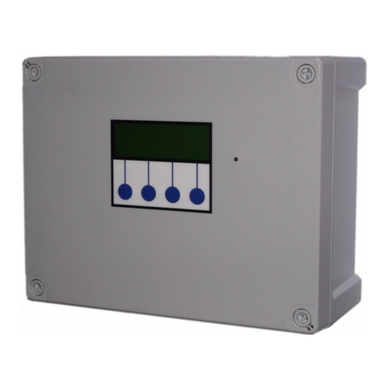
- Page 1 3P DTC200 Dosing Tank Controller Installation and Operation Manual DTC200 V1.20 Page 1 22/01/20...
-
Page 2: Table Of Contents
Wipe Configuration (Wipe Config)....................12 Restart.............................12 Troubleshooting............................13 Fuse Listing...............................14 Inputs (left to right) – Con1........................14 Pressure Sensor Inputs (left to right).......................14 BMS Output..............................15 Pump/Valve Control Outputs (left to right).....................15 Specifications..............................16 Control Panel..............................16 Switched Outputs (pump/solenoid control)....................16 DTC200 V1.20 Page 2 22/01/20... -
Page 3: Installation
1 x Wall mounting brackets Layout DTC200 is a wall mounted control panel designed to control 3 pumps or valves at 230VAC single phase, or any voltage via external relays/contactors. No fluid passes through the control unit itself and it’s location in relation to other equipment is only constrained by cable distances. - Page 4 Other types or sensor or traditional float switches may be used as long at they produce a closed circuit when dry and open circuit when immersed. Cables extension is straightforward, shielded cable is recommended for distances exceeding 10m or wiring runs in close proximity to other power circuits. DTC200 V1.20 Page 4 22/01/20...
-
Page 5: Control Panel Mounting (Without Use Or Mounting Brackets)
Mark drilling points on the wall accordingly. Withdraw the casing from the wall and drill holes appropriate for your selected fixings.Control Panel Mounting (using mounting brackets) Attach the 4 mounting brackets to the rear corners of the enclosure and then screw the whole assembly to the wall. DTC200 V1.20 Page 5 22/01/20... -
Page 6: Connections
LNE. Terminal con6 supplies power to fill the tank, con7 for the chemical dosing pump, con8 drains the tank con9 may optionally be used for a mixer/agitator/aerator to assist the reaction. The terminal blocks are socketed and can be withdrawn from the PCB for ease of access. DTC200 V1.20 Page 6 22/01/20... -
Page 7: Alarm Relay Connection
For cable lengths exceeding 10m a shielded cable is recommended particularly is the cable is run near to mains power circuits, this will help to prevent induction of stray voltages from nearby circuits which may cause false readings. DTC200 V1.20 Page 7 22/01/20... -
Page 8: Operation
Do not attempt to repair any part of the circuit board. Refer to the manufacturer for advice. Description of Operation DTC200 is a time-delay based controller for chemical dosing of fluids within a processing tank. The operation cycle consists of tank filling, tank dosing, reaction delay, and tank draining. - Page 9 DTC200 V1.20 Page 9 22/01/20...
-
Page 10: Startup Screen Menus And Functions
Once the timer expires the tank will continue to fill and once full the reaction delay will start. In the event that the tank fills before dosing is completed then the dosing will continue until it’s time is completed and the reaction delay begins. This mode reduces the total duration of the processing cycle. DTC200 V1.20 Page 10 22/01/20... -
Page 11: Timers
Allows you to view the state of the level sensors or activate the outputs manually. Inputs Displays the state of all 5 inputs, note than input 5 is unused in this product. 0 = closed circuit (no fluid) 1 = open circuit (sensor immersed) DTC200 V1.20 Page 11 22/01/20... -
Page 12: Outputs
Note – Any options set during commissioning will be lost and need to be re-entered. Restart Restarts operation of the system. DTC200 V1.20 Page 12 22/01/20... -
Page 13: Troubleshooting
PCB if necessary Tank shows full or Sensors disconnected Check wiring overflow condition constantly Incorrect sensor function or Ensure sensors show closed orientation circuit when dry, open circuit when immersed. Low Alarm Sensor disconnected Check wiring DTC200 V1.20 Page 13 22/01/20... -
Page 14: Fuse Listing
2 – Low (tank empty) 3 – High (tank full) 4 – Overflow (installed above high level sensor) 5 – unused Pressure Sensor Inputs (left to right) Con3 (left) – unused Con4 (right) – unused DTC200 V1.20 Page 14 22/01/20... -
Page 15: Bms Output
Type – Non contact relay Terminals – Common, Normally Open, Normally Closed Power Rating max 16A 250Vac Pump/Valve Control Outputs (left to right) 1 – Tank filling 2 – Tank Dosing 3 – Tank Draining 4 – unused DTC200 V1.20 Page 15 22/01/20... -
Page 16: Specifications
7w (control panel only) Operating temperature range 0 to 40 degrees celsius Ingress Protection (EN60529) IP65 Electrical Insulation Class 2 Switched Outputs (pump/solenoid control) Voltage 220-240vac 50hz (exact voltage as supply voltage) Current 10A (peak 16A) DTC200 V1.20 Page 16 22/01/20...
Need help?
Do you have a question about the DTC200 and is the answer not in the manual?
Questions and answers