
Summary of Contents for Global Industrial 298625
-
Page 1: Table Of Contents
Air Chain Hoist User Manual Model no. 298625, 298626, 298627 Table of Contents General Data pg. 2 Disassembly & Reassembly Safety Information pg. 4 • Disassembly pg. 8 Installation & Set up pg. 4 • Reassembly pg. 11 Operation pg. 6 •... -
Page 2: General Data
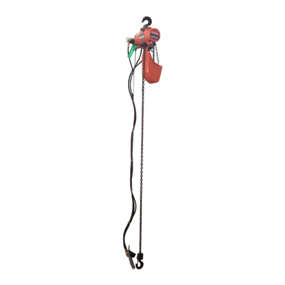
Global Industrial Hoists are high quality hoists made with a tough, compact housing for easy operation, transportation and storage. These are made for long lasting use in industrial environments. Very efficient with different speed controls and ability to lift different load capacities. - Page 3 Hoist Dimensions Dimensions [inches] Ref. 298625 298626 298627 15.25 15.25 15.25 10.25 10.25 10.25 4.75 4.75 4.75 1.75 1.75 1.75 7.0625 7.0625 7.0625 5.0625 5.0625 5.0625 0.9375 0.9375 0.9375 2.1875 2.1875 2.1875 5.6875 5.6875 5.6875 1/2TON...
-
Page 4: Safety Information
SAFETY INFORMATION PLEASE READ THOROUGHLY AND CAREFULLY. IMPROPER OPERATION OR FAILURE TO FOLLOW THESE PRECAUTIONS COULD RESULT IN SERIOUS INJURY. DO NOT operate a damaged hoist. DO NOT modify the hoist in any way. DO NOT lift more than max capacity. DO NOT lift over people, or transport people. - Page 5 Connecting Hoist to Air Source: 1. Connect hoist to a filtered and lubricated air source with a least 1/2” I.D (see image 2) 2. If the hoist is connected with trolley, the hose must be long enough to reach from air source.
-
Page 6: Operation
OPERATION The operator should be a trained professional and is responsible for safe use with these hoists. They must follow the safety guidelines mentioned on page 5 to prevent damage or injury. 1. Inspect all connections between side hoist frame, hooks, and structural support. Check all parts (brake, hoist, chain, pins) to make sure there is no damage/distortion. -
Page 7: Maintenance & Inspection
MAINTENANCE & INSPECTION Periodic maintenance checks on the hoist components are recommended to make sure there is no damage. Do not attempt to repair defective parts. Only Global approved that meet specifications for strength and dimensions must be used. Please contact Global Industrial Customer Service (1-800-645-2986) for replacement chains, hooks, etc. -
Page 8: Disassembly & Reassembly
DISASSEMBLY & REASSEMBLY For ease of disassembly, the following disassembly steps may not, where conditions permit, be completed before hoist is removed from its overhead suspension or disconnected from its air supply. If the hoist is in use, remove the chain container. Remove lower block and load chain assembly. - Page 9 4. Carefully pry brake spring up evenly with a screwdriver until spring is about halfway off to remove it. Using brake spring spreader (Image 12), take out spring from brake arms. 5. Take out brake shoes. Make sure not to lose steel fulcrum balls.
- Page 10 Removal and Disassembly of Air Motor 1. Place entire unit on motor end and lift frame straight up as shown to remove air motor from hoist frame. DO NOT tap on end of motor shaft since it will destroy critical rotor alignment and damage motor.
-
Page 11: Reassembly
Image 15 Removing Cap Screw Image 16 Removing Brake Wheel and Securing Bearing Clamp Plate Ball Bearing Assembly Image 17 Removing gear plate and Image 18 Removing internal gear, chain intermediate gears sprocket and ball bearing. Reassembly Follow the procedure that is in reverse order of the disassembly steps to reassemble hoist Assembly of Motor CAUTION 1. - Page 12 Assembly of Control Head Observe these precautions at reassembly of control head and throttle valve: 1. Lightly oil throttle valve and bushing with SAE 20 oil. Assemble valve with threaded hole facing slot at bottom of bushing in housing (Image 19) if shifter pin was removed from valve.
- Page 13 Assembly of Brake Replace brake shoes if the brake linings show excessive wear. The brake wheel assembly goes into position first and is fastened in place by the four screws in reassembling the brake (See “Disassembly and Reassembly”, Page 8, Image 16). Then put the steel fulcrum balls in their receiving cup, using a small amount of thick grease to hold them in place.
-
Page 14: Testing Hoist
Testing Hoist Hoist should be tested to insure proper operation after completion of assembly and before placing hoist in service. Test as follow: Suspend hoist from an overhead supporting member of sufficient strength to carry combined weight of hoist and rated load; connect to air supply of correct pressure;... -
Page 15: Pendant Throttle Control Assembly
Image 22 Installing Single Reeved Load Image 23 Installing Double Reeved Chain (300, 500, and 1000 lb. models) Load Chain (2000 lb. Model) Pendant Throttle Control Assembly The pendant throttle control assembly will require some maintenance attention after long periods of use. To service the control handle assembly, cut off air supply, bleed air from hoist and control, and disconnect hoses and strain cable at control handle. -
Page 16: Inspection Schedule & Maintenance Report
INSPECTION SCHEDULE AND MAINTENANCE REPORT HOIST MODEL NO. INSPECTION FREQUENCY 298625 298626 298627 RATED LOAD: 300lb. 500lb. 1000lb. MONTHLY ANNUAL SEMI-ANNUAL LOCATION IN PLANT: INSPECTED BY: DATE: *Recommen- CONDITION COMPONENT, UNIT OR PART (Check column best indicating condition when CORRECTIVE ACTION NOTES... -
Page 17: Parts List
Parts List * Denotes Parts Aviliable Quantity Ref. Description 1000 2000 Bolt -Suspension Bracket Lockwasher -Shakeproof, External (8mm) Nut -Hex, Cadmium Plated (M8×1mm) Hook and Bracket Assembly - Suspension (Includes Ref. No. 5 thru 13) Hook and Nut Assembly -Upper (Includes Ref. No. 6) Latch Kit Bushing -Machinery Bracket - Suspension... - Page 18 Ref. 1000 2000 Description Shaft -Control Bushing -Oilite, Control Shaft Chain -Load, Coil Type (11’-5” Lg.) 1 (10’) 1 (10’) 1 (10’) Chain -Load, Coil Type (22’-7” Lg.) 1 (20’) 1 (20’) 1 (20’) 1 (10’) Chain -Load, Coil Type (44’-8” Lg.) 1 (20’) Lever -Control Block Assembly -Lower (1/4 Ton) (Incl.
- Page 20 Ref. no Description Quantity Ring-Retaining, External (25mm) Bearing Assembly-Ball, Sprocket (ISO3290-6005-2Z) Guide and Stripper Assembly-Chain (Coil Type Only) Sprocket -Chain (Coil Type Only) Lockwasher -Shakeproof, Internal (6mm) Screw-Button Head (M6 16mm) × Bearing Assembly-Ball,Sprocket (ISO3290-6006-2Z) Plate-Clamp, Bearing Gear-Internal Nut-Spindle (UNF3/4-16 Self-Locking) Shaft -Intermediate Gear Bearing Assembly-Needle (B-97) Gear -Intermediate...
- Page 21 Ref no. Description Quantity Motor Assembly Screw -Hex Socket Button Head (M5×12mm) Bearing – Ball (ISO3290-6002-2Z) Plate -End, Dead Blade -Rotor Rotor and Shaft Assembly Pin –Spring (5×20mm) Pin –Spring (5×16mm) Body Plate -End, Drive Ring –Retaining (32mm)
- Page 23 Ref. no Description Quantity Cylinder Assembly -Control, Pendant (Incl. Ref. 2-10 and 15) Ring -Lock, Cylinder Screw -Set, Hex Socket (M5×10mm) Cap -End, Cylinder Spring -Piston, Cylinder Seal -”U” Ring, Piston Piston -Control Cylinder Cylinder -Pendant Control Seal -”O” Ring, Piston Stem (ISO3601.1-6×1.8mm) Retainer -”O”...
- Page 24 Ref. no Description Quantity Guard -Control Lever Gasket (ISO3601.1-10.6×1.8mm) Spring Body -Swivel, Inlet (3/8” -18 N.P.T.) Seal -”O” Ring, Inlet Swivel (ISO3601.1-16 2.65mm) × Bushing -Inlet Swivel Ring -Retaining, External Gasket -Inlet Swivel Bushing (Brass) (JB982-24) Screen -Inlet Swivel Screen -Muffler Muffler -Exhaust Gasket -Air Seal, Motor End Plate Gasket -Control Head to Frame...
-
Page 25: Troubleshooting
Troubleshooting Issue Probable cause(s) Solution Brake lining oily, glazed or badly worn. Remove brake arms and replace with new. Hoist can’t hold Brake out of adjustment. Adjust brake. load in suspension. Excessive overload. Reduce load. Shut off air - disconnect air hose - clean Clogged air intake screen.
Need help?
Do you have a question about the 298625 and is the answer not in the manual?
Questions and answers