Table of Contents
Advertisement
Advertisement
Table of Contents

Summary of Contents for Furness controls FCO770
- Page 1 FCO770 LEAK DETECTOR USERS GUIDE Please read carefully before using. Manufactured by: FURNESS CONTROLS LIMITED Beeching Road, Bexhill, East Sussex, TN39 3LJ, England. Telephone (01424) 730316. Fax: (01424) 730317 Email: sales@furness-controls.com Web Site: www.furness-controls.com...
-
Page 3: Table Of Contents
TEST DATA MENU ............................42 LEAK TEST PARAMETERS.......................... 43 BLOCKAGE TEST PARAMETERS....................... 48 PERMFILL TEST PARAMETERS ......................... 51 RAMP TEST PARAMETERS ......................... 53 DUMP TEST PARAMETERS......................... 54 COARSE LEAK TEST PARAMETERS ......................56 BATCH SETTINGS MENU..........................59 FCO770 Users Guide Issue 1 Page 3... - Page 4 ERROR MESSAGES ............................94 SPECIFICATION .............................. 96 PRESSURE RANGES ............................. 96 LEAK RANGES............................... 96 DIMENSIONS ..............................97 BENCH MOUNTED CASE..........................97 RACK MOUNTED CASE ..........................97 RACK MOUNTED CASE ..........................98 INDEX ................................. 99 Page 4 FCO770 Users Guide Issue 1...
-
Page 5: Revision Record
REVISION RECORD Issue Date Summary of changes 1 16/05/12 First Release FCO770 Users Guide Issue 1 Page 5... -
Page 6: Safety Notes And Recommendations
Particle = < 0.1micron, Dew-point = < 3°C, Oil = < 0.1mg/m (0.1ppm) The filter kit (Part number M1706) supplied by Furness Controls consists of a particulate filter and a coalescing filter. This will remove solid particles to 0.01microns and oil concentration down to 0.01ppm. Neither of these will remove water vapour and an airline drier or desiccant filter (Part number M1737) is required for this. -
Page 7: Introduction
LAN. Communications may be used for configuration and data logging. Maintenance Early Warning System to aid planned maintenance. Email facility. The FCO770 may be configured to send an email over the optional LAN if a fault or maintenance warning occurs. -
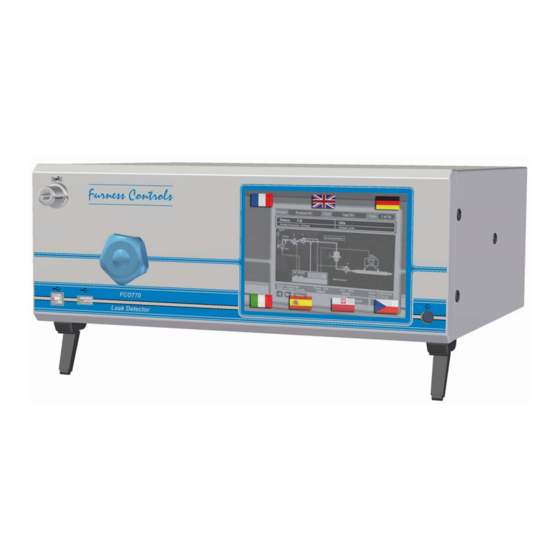
Page 8: Housing
The FCO770 is housed in a steel bench-top case having two extending front feet that allow the case to be tilted so that the front panel can be seen more easily. Case extensions are available to allow the FCO770 to be mounted in a 19” x 3U rack housing. - Page 9 Pushing the connection plug into the port connects the calibration equipment. The button on the top of the port must be pressed to release the plug. Plugs can be obtained from Furness Controls or their distributors, part No A4667.
-
Page 10: Rear Electrical Connections
The external 24V DC supply connects via this 2 way detachable screw-terminal. The Instrument is protected against reverse polarity and has an internal auto-resetting fuse. The Furness Controls 24V supply is grounded. If a different supply is used it must be grounded. Input Terminals The input terminals are used for jig interfacing and when the instrument is configured for remote control. -
Page 11: Rear Pneumatic Connections
The air supply port is used to operate the instruments internal valves. It accepts 6mm O/D tubing. Clean dry air is required at a pressure of between 5bar (72PSI) and 10bar (145PSI). Regulator Supply External filtering must be provided. See “Safety notes and recommendations” FCO770 Users Guide Issue 1 Page 11... - Page 12 These three optional pneumatic outputs may be programmed for a variety of applications. Some of these ports may not be available if used for internal valves, e.g. for functions such as air saving or dual regulator selection. Page 12 FCO770 Users Guide Issue 1...
-
Page 13: Methods Of Leak Detection
A leak on the Test -ve port will show as a -ve leak. Leaks may be displayed as a flow reading rather than differential pressure. The FCO770 measures the leak as a pressure drop and then calculates the flow reading. The calculation relies on the test volume being known as well as the pressure drop in a given time. -
Page 14: Bell System
By applying a low pressure to the bell from the leak detector the integrity of the bell can be checked. If a seal is damaged or missing the FCO770 it will show as a negative leak reading. Since both positive and negative fail levels can be set on the FCO770, the system guarantees that every test is valid. -
Page 15: Installation
NOTE: All connections to the 'Test +' or the 'Test -' ports must be leak tight. Metal to metal connections should be sealed using a known good sealing compound, not P.T.F.E. tape. The FCO770 Users Guide Issue 1 Page 15... -
Page 16: Test Item
The outputs are active high transistors (i.e. switching the positive supply). The current per output must not exceed 120mA. If it is necessary to have mains operated lamps or any other high voltage or heavy current device, the outputs should be used to drive external relays. Page 16 FCO770 Users Guide Issue 1... -
Page 17: Wiring Considerations
It is very important that any inductive load is suppressed to prevent these voltages being generated. The transistor outputs from the FCO770 are fitted with suppression diodes and it is not necessary to add further suppression to the inductive load. However, if an inductive load is being activated from a PLC or another relay, then suppression must be fitted. -
Page 18: Basic Operation
BASIC OPERATION The FCO770’s settings may be viewed or set by pressing the ‘Menu’ soft button to toggle onto the instruments menu screen. The Menu button can be pressed at any time to return to the instrument main screen. See menu screen shot below:... -
Page 19: Menu Navigation
Text Entry The FCO770 has a number of menus that have text to enter, e.g. Test I/D, Product I/D etc. When editing text you will see a dialogue input box like this: The text to edit appears highlighted blue in the cream coloured window surrounded by a customised QWERTY keypad. -
Page 20: Menu Navigation Diagram
GLOBAL LANGUAGE SETTINGS OPERATION PRODUCT NUMBER ALTER PRODUCT LK RESOLUTION (DIGITS) PR RESOLUTION (DIGITS) FILL ON FAIL ENABLE FAIL 2 ENABLE PREFILL LEAK AT END OF TEST RESET ON PASS RESET ON FAIL RESET DELAY (S) A.Z. DELAY (S) STATUS LINE START/RESET CONFIGURE VENT SENSOR... -
Page 21: Main Operator Displays
LEAK ZERO (%) * live value CALIBRATION DUE (DAYS) * live value * Live value for the corresponding limit shown above GREEN = OK, RED = OUT OF LIMITS LOCK SECURITY SECURITY CODE OFF BUTTON FCO770 Users Guide Issue 1 Page 21... -
Page 22: Main Operator Displays
The FCO770 run time displays that are usually left showing when a test is in progress comprise of an upper and lower status window and various selectable main window displays shown between. The upper status window typically will look as shown below:... - Page 23 Dashed test stage division lines indicate when a new test stage starts • The graph plot will automatically clear when a test cycle ends and its axis will automatically scale itself when a test starts. FCO770 Users Guide Issue 1 Page 23...
- Page 24 • The test selected for monitoring and the size and number of bars displayed along the horizontal axis can be defined in the options dialogue box by pressing the ‘Options’ button, as shown below: Press the # buttons to change corresponding settings. Page 24 FCO770 Users Guide Issue 1...
- Page 25 • Shows a list of Product results that can be individually interrogated to show logged data for the tests made. The FCO770 has a powerful data logging system that runs seamlessly throughout product testing, capable of storing in excess of 1 million test and graph plots.
- Page 26 Notice that all tests and their data are shown on separate lines, with the test in question highlighted using the familiar blue background. This makes for quick and easy viewing of all product test data on a single screen. Page 26 FCO770 Users Guide Issue 1...
- Page 27 • The Last Results tab is used to configure how logged data is recalled from the FCO770’s massive internal repository, before being presented to the user. • Selecting Recall setting: Current will ensure that logged data will get recalled up to the current date.
- Page 28 • The Data logging tab is used to set the range of dates included when writing logged data from the FCO770’s repository to a USB memory stick. From and To dates can be defined directly using the corresponding calendar icon buttons. Alternatively by checking the boxes appropriately, data can be written from the oldest and/or the most current logged date.
- Page 29 • The Memory Usage tab shows the capacity of the FCO770’s data logging repository and the current usage. All data written to the repository is compressed to save space. • DATA units are consumed at the rate of approximately 1 per single test and less for products containing multiple steps.
-
Page 30: Global Settings Menu
BCD INPUT: Product selection is made from the external BCD inputs. LEAK DISPLAY RESOLUTION • The FCO770 has a 4-digit display for the leak value, which may give too much resolution for some applications. To reduce the apparent resolution you may set this parameter to the number of digits to round to, e.g. - Page 31 Yes: automatically resets to 'Ready' if a Pass occurs. The result is held for the Reset Delay time before being cancelled. You may start a new test at any time. FCO770 Users Guide Issue 1 Page 31...
- Page 32 Blank: the status line is unused. o Counters: shows pass and fail counters. o %Counters: show pass and fail counters as a percentage o Barcode: shows the last scanned barcode o Serial No.: shows the current serial number. Page 32 FCO770 Users Guide Issue 1...
-
Page 33: Configure Inputs Menu
Start and Reset signals may also be provided by Fbus Communications or a barcode reader. VENT SENSOR • When a vent valve with a position sensor is used, the FCO770 can monitor the sensor to ensure that the valve has operated before running a test. • Options: o No: The sensor is not monitored. - Page 34 • The FCO770’s electrical inputs are configurable for many functions. To simplify the task of setting up the FCO770, groups of related functions may be assigned to the physical inputs in banks of four. Note that inputs 1-4 default to basic remote control functions but they may be reprogrammed for other purposes if required.
- Page 35 Zero the pressure transducer when the instrument is at standby. You must ensure that pressure is removed before using this. o JIG SENSOR o VENT SENSOR These may be useful when the Basic Functions bank is programmed for alternate use. FCO770 Users Guide Issue 1 Page 35...
- Page 36 These may be used for remote control when the Basic Functions bank is programmed for an alternate use. Reset is fail-safe active low. o RESET+ This active high reset input is for applications that require it. This is not normally recommended. Page 36 FCO770 Users Guide Issue 1...
-
Page 37: Configure Outputs Menu
• The FCO770’s electrical outputs are configurable for many functions. To simplify the task of setting up the FCO770, groups of related functions may be assigned to the physical outputs in banks of eight. Note that two banks are fitted as standard. There is a purchase option for enhanced i/o for an additional two banks. - Page 38 These may be used internally for some options, or made available via rear panel ports. • Options: See the output function list on page 40. Page 38 FCO770 Users Guide Issue 1...
-
Page 39: I/O Functions Menu
COMBO x INPUT 1 COMBO x INPUT 2 (where x is 1, 2, 3, or 4) • Define the signals to input to the combo function. • Options: See the output function list on page 40. FCO770 Users Guide Issue 1 Page 39... - Page 40 Note that when a Fail 2 output is active the associated Fail 1 output is also active. Gross fails activate the Fail 2 outputs. Pressure Gross also activates all +Fail and –Fail outputs. Page 40 FCO770 Users Guide Issue 1...
-
Page 41: Product Data Menu
• When there is more than one step, define the conditions required to continue to the next step. If the condition is not met the instrument will fail the product and terminate the test. • Options: RESULT, PASS, FAIL 1, PASS/FAIL1, FAIL, START FCO770 Users Guide Issue 1 Page 41... -
Page 42: Test Data Menu
Any variations of the prefill pressure may be compensated for, giving a more sensitive gross leak check. Page 42 FCO770 Users Guide Issue 1... -
Page 43: Leak Test Parameters
LEAK UNITS • Choose the engineering units for the leak display. The FCO770 can display the leak in either pressure units, pressure rate units or flow units. See the specification table on page 96 for available units. - Page 44 • When used, these set the higher positive and negative levels at which the instrument will indicate a failure. When the measured leak exceeds the set level the appropriate front panel fail lamp will flash and the FAIL and “+FAIL 2” or “-FAIL 2” signals are activated. Page 44 FCO770 Users Guide Issue 1...
- Page 45 • Only displayed when flow units are selected in the Global Settings menu. • The FCO770’s leak test measures differential pressure. In order to display the leak correctly in flow units, e.g. cc/min, the instrument needs to know the volume of the test item in cc.
- Page 46 • Note that the input function must be defined in the i/o configuration menu. • Options: o NO: External fail is not used for this test. o ON: The input is expected to be active during the stabilisation time. Page 46 FCO770 Users Guide Issue 1...
- Page 47 OFF: The input is expected to be inactive during the stabilisation time. o CHANGE: The input is checked at standby and is expected to change state before the stabilisation stage starts. FCO770 Users Guide Issue 1 Page 47...
-
Page 48: Blockage Test Parameters
• When this is enabled the fill valve remains active during the test time. This allows a back-pressure test to be performed in cases where the flow is too high for the blockage test to discriminate adequately when the pressure source is removed. • Options: No, Yes. Page 48 FCO770 Users Guide Issue 1... - Page 49 FAIL LOW level checks for a gross leak. Set FAIL LOW to zero to disable the gross leak check. POSITIVE TEST PRESSURE FAIL FAIL LOW PASS FAIL FAIL HIGH PASS PASS FAIL HIGH FAIL PASS FAIL LOW FAIL VACUUM TEST PRESSURE FCO770 Users Guide Issue 1 Page 49...
- Page 50 • When the feedback inputs are not used for jigging they may be used to check signals from test components. If the correct feedback is not supplied within the feedback timeout period then the test ends with a FEEDBACK FAIL result. Page 50 FCO770 Users Guide Issue 1...
-
Page 51: Permfill Test Parameters
• The vent time should be set if an external vent valve is fitted to the system. The time must be long enough to allow the pressure in the test item to decay to a safe level to ensure that the test item is not unclamped while pressurised. FCO770 Users Guide Issue 1 Page 51... - Page 52 • When the feedback inputs are not used for jigging they may be used to check signals from test components. If the correct feedback is not supplied within the feedback timeout period then the test ends with a FEEDBACK FAIL result. Page 52 FCO770 Users Guide Issue 1...
-
Page 53: Ramp Test Parameters
HOLD OFF • Sets the time delay after the test has started to allow valves to actuate and the pressure ramp to start. This time is normally very short, typically 0.1 second. FCO770 Users Guide Issue 1 Page 53... -
Page 54: Dump Test Parameters
– this allows for a more sensitive test. This can be disabled to aid commissioning or if it necessary to display the actual pressure rather than a compensated value. • Options: No, Yes. Page 54 FCO770 Users Guide Issue 1... - Page 55 This is active during standby, and turned off after the jig delay and prefill timers. Traditionally, the jig or vent output is used to isolate the pressure source from the reference volume, but the FCO770’s prefill output provides a more flexible solution. PREFILL TOLERANCE •...
-
Page 56: Coarse Leak Test Parameters
• Only used with auto prefill and only displayed if auto prefill is used. • This is used to detect when to stop filling. Tolerance checking at standby must be disabled for auto prefill. Page 56 FCO770 Users Guide Issue 1... - Page 57 • Set the required vent time to allow the test item to vent through an external vent valve. This should be set long enough to ensure that the test item is not unclamped while pressurised. FCO770 Users Guide Issue 1 Page 57...
- Page 58 OFF: The input is expected to be inactive at the end of the test time. o CHANGE: The input is checked at standby and is expected to change state before the test time ends. Page 58 FCO770 Users Guide Issue 1...
-
Page 59: Batch Settings Menu
BATCH SETTINGS MENU The FCO770 allows you to test in batches. When the required number of tested items has been reached the instrument will display “BATCH COMPLETE” on the status line and stop testing. A runtime screen shows batch counters and status. An electrical or pneumatic output may be programmed to operate when the batch is complete. -
Page 60: Utilities Menu
LOAD IMAGES • The FCO770’s Default Main run time display will display up to 300 user defined colour images (1 for each test available). Whenever a test starts, and a test image has been imported for that test, it is immediately displayed on the Main display area. - Page 61 Press OK when ready. • The update file will now be copied into a temporary location on the FCO770 and you will be asked to remove the memory stick before proceeding. Click OK when ready.
- Page 62 Extended Utilities Menu. The FCO770 implements a menu interface for the setting of various commissioning and diagnostic parameters. Press the Extended Utilities Menu button to activate this menu. A menu screen similar to that below will then show: Use these buttons to navigate the menu.
- Page 63 CALCULATE VOLUME • This sub menu allows the FCO770 to calculate volume automatically, based on a known leak. A leak test on a known good item must be run with the approximate test volume and the calibrated leak attached. The result of this test should be recorded for reference purposes.
- Page 64 BACK o Note that the first character of the product i/d of the copied data is changed to ‘*’ to indicate that the data is not the original version and should be edited. Page 64 FCO770 Users Guide Issue 1...
- Page 65 • When a barcode reader is used it can be a little complex to configure. This utility helps by displaying the scanned data along with the extracted product / serial number information. A function button allows you edit the settings directly from this utility. FCO770 Users Guide Issue 1 Page 65...
-
Page 66: Fbus Settings Menu
RS232, RS485 and LAN ports. Parity is not used for the USB port. • The parity setting must be the same on the FCO770 and device being used. When using the LAN the parity must match the configuration of the LAN adaptor. -
Page 67: Barcode & Serial No
FCO770. Note that if the serial number is to be provided by a barcode the instrument will not start a new test until a serial number has been scanned. - Page 68 This allows a variable length serial number to be used, up to a maximum of 20 characters, although the mask is limited to 16 characters. The mask can be used to set the minimum length. • Options: 0 to 20. Page 68 FCO770 Users Guide Issue 1...
- Page 69 If the instrument is reset when waiting for the fail code to be scanned the default Product Fail code 10 will be used. • Options: No, Yes. FCO770 Users Guide Issue 1 Page 69...
-
Page 70: Serial Numbering
SERIAL No. • This is the auto-incrementing number. You may set the initial value, and thereafter it will be incremented after each test according to the Serial No. Type setting. Page 70 FCO770 Users Guide Issue 1... -
Page 71: Printer Settings Menu
PC. o NO: The FCO770 does not send a line-feed at the end of a line. If the printer does not add a line feed then all lined of print are printed on top of each other. - Page 72 Up to 20 blank lines may be added. SEND EOF • When a PC or PLC is capturing printed data from the FCO770 it may be useful to add an “End Of File” character at the end of the printed data. The EOF character may be represented as <Ctrl Z>, 0x1a, chr$(26) etc.
- Page 73 Any of the text lines 1-6 may be placed here instead of the header using special characters at the start of the text line. This is rarely necessary but may help with unusual printing requirements. The optional blank lines will be after this section. FCO770 Users Guide Issue 1 Page 73...
-
Page 74: Warning System
Cycle Count: the number of test cycles since this counter was last reset. It is normally only reset after the instrument’s internal valves have been serviced. It is expressed in millions. o Latency: This is the time taken for the internal valves to operate. Air supply Page 74 FCO770 Users Guide Issue 1... - Page 75 If the value is negative then calibration is over-due. • WARNING CODES When a warning occurs it is shown on the FCO770’s lower status window. A flashing message will appear with one of the following codes: o M01: Cycle Count...
-
Page 76: Security Menu
SECURITY MENU The FCO770 may be configured to stop unauthorised changes to the test parameters. If you select this menu when the instrument is locked you will be asked to enter the security code before continuing. LOCK • Lock or unlock data entry. When locked you will be asked for a security code before changing data. -
Page 77: Input/Output Connectors
The voltage between the + and 0V pins must be within the range of 12 to 45VDC. Ensure correct polarity. Each output can source up to 120mA. If higher voltage or current is required use an external relay. FCO770 Users Guide Issue 1 Page 77... -
Page 78: Control Inputs
Note that the reset input is fail-safe so that it must be made before instrument can start when remote control is enabled (I/O Configuration menu). See the input connection method diagrams in the Interfacing section of this guide. Page 78 FCO770 Users Guide Issue 1... -
Page 79: Rs232 Output
* 6 DSR 4 DTR 20 DTR * These are not required but are normally made in a crossover cable. This type of cable is often referred to as a “Null Modem” cable. FCO770 Users Guide Issue 1 Page 79... - Page 80 1 CD * 6 DSR 20 DTR 4 DTR * These are not required but can be connected to make the cable the same both ends when connecting to a 9-way computer port. Page 80 FCO770 Users Guide Issue 1...
-
Page 81: Rs485 Output (Optional)
9-way D connector to terminal boxes can be used to allow a spur to be taken from the simplify the wiring. TX A TX B RX A RX B GND main cable to each device. FCO770 Users Guide Issue 1 Page 81... -
Page 82: Interfacing To A Jig
P2 (Vent) SUPPLY MIN. 5BAR REGULAT ED MAX. 10BAR AIR OUT REGULAT OR REGULAT ED SUPPLY AIR IN T EST 4mm O /D TEST ITEM V1,V2 = MO1308 VENT VALVE REF ERENC E ITEM Page 82 FCO770 Users Guide Issue 1... -
Page 83: Configuring For A Dump Test
This can be overcome by swapping the ports of V2, or using the Combo function to invert the sense of the prefill signal. FCO770 Users Guide Issue 1 Page 83... -
Page 84: Electrical Input Connection Methods
SWIT CH OR RELAY +24VDC +24VDC I/P COMMON I/P COMMON ACTIVE LOW CIRCUITS NPN PROXIMITY SWITCH/TRANSISTOR DRIVE SWITCH OR RELAY CONTACTS FCO7xx FCO7xx I/P COMMON I/P COMMON SWIT CH +24VDC OR RELAY +24VDC Page 84 FCO770 Users Guide Issue 1... -
Page 85: Control Input Circuits
At the end of the test the switch may be returned to the reset position. This method can not use the auto-reset or continue-on-start features. FUNCTION FCO770 CONNECTOR START START +24V DC RESET RESET I/P COMMON FCO770 Users Guide Issue 1 Page 85... -
Page 86: Connecting To A Plc
+24V DC CONNECT T HE OUT PUT SUPPLY AS APPROPRIAT E PLC WITH ACTIVE LOW I/P FCO7xx OUTPUTS CAN BE CONNECTED TOGETHER AS SHOWN TO GIVE AN 'OR' FUNCTION. FAIL FAIL O/P FAULT Page 86 FCO770 Users Guide Issue 1... -
Page 87: Multi-Jig Function
The FCO770 has the capability of working with up to four test jigs. This multi-jig mode is automatically enabled if any of the programmable input banks is configured for Jig Start signals. When multi-jig mode is enabled, the normal remote start signal is not used. -
Page 88: Calibrate Flow Procedure
CALIBRATE FLOW PROCEDURE When leaks are displayed as a flow reading rather than differential pressure, the FCO770 measures the leak as a pressure drop and then calculates the flow reading. The calculation relies on the test volume being known as well as the pressure drop in a given time. - Page 89 5.0 cc/min. ♦ The DISPLAY value shows the leak reading that was recorded in the last test or zero if a test was not completed. Change this if required to be the same as FCO770 leak reading. ♦ Select OK and press ENTER. The volume of the test item, test pipe and jig is calculated and displayed.
-
Page 90: Offset & Auto Tracking
Auto offset tracking allows this method to be used even when a slow drift in the transient occurs due to variations in the surrounding temperature or production rate etc. The FCO770 tracks any variation in the offset over a number of tests by digitally filtering all leak readings below the fail limit. -
Page 91: Production Procedure
The learn phase can be initiated from the instrument front panel or by an external switch contact. When an external switch is used it should be closed whilst the START button is pressed. The digital filter is reset when the product is changed. FCO770 Users Guide Issue 1 Page 91... -
Page 92: Trouble Shooting
PROBLEM: INSTRUMENT FAILS ALL TEST ITEMS. Cause: Every item is leaky, the jig is leaking, the connections from the FCO770 to the test item are leaking or the instrument has an internal leak. Action: Blank the instrument and run a test. - Page 93 There is an intermittent leak on the test system. Action: Do not use push-in air line fittings on the test line. Blank the instrument and perform a self check to ensure the FCO770 is OK. Cause: The test system has flexible components.
-
Page 94: Error Messages
ERROR MESSAGES A number of error messages can be displayed at the top of the FCO770 Status window in the event of a system or hardware failure. MESSAGE: LEAK ZERO FAULT Indicates that the zero output of the leak transducer is beyond the automatic zero limits. The transducer assembly requires re-zeroing;... - Page 95 You can check the inputs using the Utilities menu. Note if no connections are made to the BCD inputs, this will show the BCD input fault, as test number zero is invalid. FCO770 Users Guide Issue 1 Page 95...
-
Page 96: Specification
Regulated Air In........16 bar maximum, except for the 30 bar range which is a special build that accepts 35 bar maximum. Program Data Retention......> 10 Years in non-volatile memory. Weight............9kg Page 96 FCO770 Users Guide Issue 1... -
Page 97: Dimensions
DIMENSIONS 360.0 366.0 FCO770 Users Guide Issue 1 Page 97... -
Page 98: Rack Mounted Case
360.0 465.0 482.0 Page 98 FCO770 Users Guide Issue 1... -
Page 99: Index
Control Input Circuits, 85 Control Inputs, 78 Global Settings Menu, 30 Control Outputs, 77 Copy Product Data, 64 Copy Test Data, 65 Count On, 59 High Pressure, 9 Hold Off Time, 53 Housing, 8 FCO770 Users Guide Issue 1 Page 99... - Page 100 Off Button, 76 RS485, 10 Offset, 45 RS485 Connections, 81 Offset Tracking, 46, 90 Operation, 30 Operator Displays - Detailed, 23 Operator Displays - Large, 24 Security Code, 76 Output Banks, 37 Security Menu, 76 Page 100 FCO770 Users Guide Issue 1...
- Page 101 Test Parameters – Coarse Leak Test, 56 Test Parameters – Dump Test, 54 Test Parameters – Leak Test, 43 Zero Pressure, 60, 61, 62, 63 Test Parameters – Permfill Test, 51 Test Parameters – Ramp Test, 53 FCO770 Users Guide Issue 1 Page 101...
Need help?
Do you have a question about the FCO770 and is the answer not in the manual?
Questions and answers