Advertisement
Quick Links
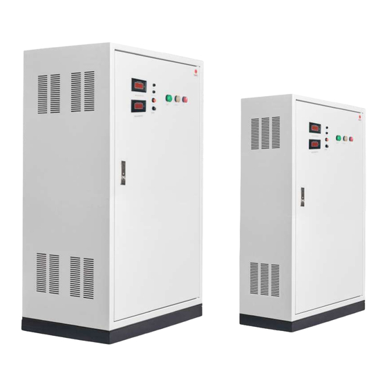
USER MANUAL
Central Battery Systems CCU 12V And CCU 24V Series
Figure
D
Features
Central Battery Systems by CCU 12V And CCU 24V Series or the central control unit is used to detect
any abnormalities of the main power distribution system. In case of error or emergency, the unit is
designed to allow the emergency lighting system to bear large loads or larger loads than that the
automatic emergency light (complete unit) can. The 12 VDC or 24 VDC unit is compatible with halogen
lamp or MR16 LED lamp. The unit installation and usage are centrally controlled so that it supplies power
to the lamp installed.
1
Advertisement

Subscribe to Our Youtube Channel
Related Manuals for Sunny CCU 12V Series

Summary of Contents for Sunny CCU 12V Series
- Page 1 USER MANUAL Central Battery Systems CCU 12V And CCU 24V Series Figure Features Central Battery Systems by CCU 12V And CCU 24V Series or the central control unit is used to detect any abnormalities of the main power distribution system. In case of error or emergency, the unit is designed to allow the emergency lighting system to bear large loads or larger loads than that the automatic emergency light (complete unit) can.
-
Page 2: Technical Speci Cations
Technical Speci cations CCU 12V Series CCU12V Series Rated Capacity 620W 720W 1000W 1100W 1400W 1900W Input Voltage 220 Vac 10% Frequency 50Hz Output Voltage 12VDC ( Battery Moed ) Battery Sealed Lead-Acid Battery Battery Rated Voltage 12 V Charging Current... - Page 3 Indicators Indicating the input voltage. AC. VOLTMETER Indicating the battery voltage. DC. VOLTMETER Indicating the status of the input under voltage or over voltage. LED H1 Indicating charging status. LED Charge/Full For testing the device’s availability (during normal circumstance) SWITCH TEST Short-circuit protection of AC input.
- Page 4 4. Shut o every Circuit Breaker for preparing to connect AC Input, Load Output and Battery. Figure showing the indications at the front of the unit 5. Connect the cables securely to the battery terminals to prevent damage (for models that does not come with the battery preconnected).
- Page 5 6. Connect the load to the terminal output of the central battery system. Check the short circuit of the load and the total wattage of each CCU 12V and CCU24V for how many outputs are there, then the output should be properly connected with the Load Output inside the cabinet at the power connector of the output of CCU 12 and CCU24 by connecting the wires must be corrected by connecting the red positive light to the positive (+) at the positive electrode (+) and the black positive light to the negative (-) at the negative electrode (-).
- Page 6 7. Connect the AC.Input cable to the Input 220 VAC terminal inside the unit. The Line cable should be connected to the L terminal, Neutral cable to the N terminal and Ground cable to the G terminal. All cable connections should be secured and no foreign objects should be in the unit that could cause a short-circuit.
- Page 7 9. Provide the unit with a 220VAC current by setting the AC Input Circuit Breaker to ON, the indicators on the unit should show the following. Figure showing the indications at the front of the unit Shows the current level at the Input to be about 220VAC. AC.
- Page 8 11. Set the AC Input Circuit Breaker to O to simulate the power outage status. The unit will display the status as follows. Figure showing the indications at the front of the unit The indicator is not showing. AC. VOLTMETER Indicating the battery voltage.
- Page 9 Malfunction indicator of AC Input (LED H.1) 1. Under Volt is AC INPUT status, power supply of 0-160VAC. The LED H.1 will turn on to indicate with red light. Figure showing the indications at the front of the unit 2. Over Volt is AC Input status, power supply over 270VAC. The LED H.1 will turn on to indicate with orange light.
-
Page 10: Maintenance
Maintenance 1. Every 1 month, to test the Backup power supply system, user can switch the AC input circuit breaker to "OFF" position for 30 minutes, then switch the AC input circuit breaker back to "ON" position. 2. Every 6 months, to test the Backup power supply system, user can switch the AC input circuit breaker to "OFF"... - Page 11 Note : Please read the manual carefully before installation and operation to understand how to properly operate the unit. For any further questions about your product IsOn Import-Export Co., Ltd. please feel free to contact SUNNY’s customer service department. 2915-2917 Ladprao Road, Klongjan, Tel. (+66) 02-948-4450-2 Bangkapi, Bangkok 10240 E-mail: service@sunnyemergencylight.com...
Need help?
Do you have a question about the CCU 12V Series and is the answer not in the manual?
Questions and answers