Table of Contents
Advertisement
Quick Links
Advertisement
Table of Contents

Subscribe to Our Youtube Channel
Related Manuals for Alto Professional APX1500


Summary of Contents for Alto Professional APX1500
- Page 1 APX1500 QUICKSTART GUIDE ENGLISH...
- Page 2 QUICKSTART GUIDE (ENGLISH) BOX CONTENTS APX1500 Power cable Quickstart Guide Safety & Warranty Information Booklet QUICK SETUP Make sure all items listed in the BOX CONTENTS section are included in the box. READ SAFETY & WARRANTY INFORMATION BOOKLET BEFORE USING THE PRODUCT.
- Page 3 REAR PANEL DIAGRAM PUSH PUSH COOLING FAN- This fan secures cooling for the amplifier. The airflow is from front to rear. The fan speed is electronically regulated depending on the temperature of the power devices. Do not block these fan grills or mount the amplifier in an enclosed rack, which could cause the amplifier to overheat.
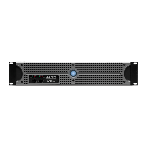
- Page 4 FRONT PANEL DIAGRAM POWER SWITCH – Turns the amplifier on/off. POWER LED – Illuminates when the amplifier is on. LED METERS – Indicates the audio signal level. This LED will light up when the signal at the output is at least - 20 dB.
- Page 5 OPERATION IN STEREO MODE The APX1500 provides three operating modes: stereo mode, parallel (mono) mode and bridged mode, you can decide each specific operating mode according to your actual application circumstance. In STEREO MODE, channel 1 and channel 2 operate independently (as a conventional stereo amplifier). The channel 1 input signal will be output from the channel 1 output connectors, and the channel 2 input signal will be output from the channel 2 output connectors.
- Page 6 • It is a good idea to mount this in the bottom of a rack frame. Supporting the back of the unit may be necessary for portable or road use. The APX1500 mounts into a standard 19u rackmount. • ALTO amplifiers are well shielded; however, mounting low-level electronics some distance away from power amplifiers is common practice to reduce the possibility of electromagnetic interference into the low level units, which may sometimes be unusually susceptible to picking up such interference.
- Page 7 SPECIFICATIONS POWER SPECIFICATIONS • Continuous power @ 0.5% THD, both channels driven, 230V: o 4Ω: 2 x 550W o 8Ω: 2 x 350W • Power EIAJ@ 1% THD, both channels driven, 230V: o 4Ω: 2 x 750W o 8Ω: 2 x 370W •...
- Page 8 www.altoprofessional.com MANUAL VERSION 1.2...
Need help?
Do you have a question about the APX1500 and is the answer not in the manual?
Questions and answers