Table of Contents
Advertisement
Quick Links
Advertisement
Table of Contents

Summary of Contents for StereoVision FS4000
- Page 1 Fire Control Panel FS4000 INSTRUCTION MANUAL Revision 4/02.11...
-
Page 2: Table Of Contents
Contents Introduction ..........................Terminology ........................... Function ..........................Technical features ......................... 4.1 Fire alarm lines ........................4.2. Current thresholds for ......................4.3. Controllable output for fire condition ................... 4.4. Relay output for fault condition ................... 4.5. Performance ........................4.6. Indications of registered events ..................4.7. - Page 3 Delay of outputs ........................User configuration of outputs ....................Installation and initial start of the fire control panel .............. 14.1. To mount the fire control panel ..................14.2. Periphery devices assembly ..................... 14.2.1. Mounting periphery devices to controllable outputs ............19 14.2.2.
-
Page 4: Introduction
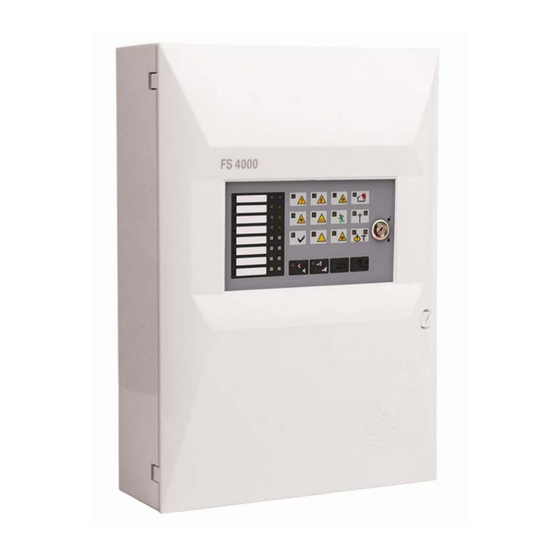
Fire Control Panel FS4000 1. Introduction Fire control panel FS4000 is an up-to-date, highly reliable, multifunctional and versatile unit. It is designed to receive signals from manual call points and automatic fire detectors, releasing sound and light indication. The fire control panel provides options for connection of external signal and executive units. -
Page 5: Function
FIRE CONDITION FIRST STAGE when authomatic detectors are activated at the same time in two lines. 3. Function Fire control panel FS4000 is designed to operate with conventional automatic fire detectors and manual call points. The panel has outputs provided for external executive devices. The unit is produced in four versions: ♦... -
Page 6: Relay Output For Fault Condition
Fire Control Panel FS4000 4.4. Relay output for fault condition: 4.4.1. Relay outputs for fire condition Number Type - potential-free, switching with independent control Electrical characteristics - 3А/125V AC, 3A/30V DC 4.4.2. Relay output for fault condition Number Type - potential-free, switching Electrical characteristics - 3А/125V AC, 3A/30V DC... -
Page 7: Power Supply To External Devices
6. General information 6.1. Access levels There are 4 levels of access to the variable indications and control functions of FS4000 6.1.1. Access level 1 All persons who would presumably find out and react to alarm for fault condition or fire condition have access to level 1. -
Page 8: Indications And Buttons For Control
Fire Control Panel FS4000 − Duty Mode; − Fire condition; − Fault condition; − Disabled component; − Test. To enter Access level 2 unlock place the key in open condition The following features are accessible: − exit of fire condition (see p.8);... - Page 9 Fire Control Panel FS4000 Conditions of the fire control panel Indication Fault condition - Indicator Fault in mains supply - Fault in mains supply continuous yellow light Fault condition - Indicator Backup battery fault - Fault in the backup batteries or in the charger...
-
Page 10: Duty Mode Configurations - General Information
Fire Control Panel FS4000 Table 2 Condition of the fire Access Means of control Operation control panel level Button Reset Fire condition Level 2 Exit of Fire condition - if outputs for fire condition are activated – Button Outputs to suppress the outputs;... -
Page 11: Conditions Of The Fire Control Panel
). The aim is to signal for forced evacuation if necessary. 7.4. Additional option In FS4000 there is opportunity for configuring line(s) in a definite way so that if signal for Fire condition, the Fire Control Panel enters directly in Fire condition 2 stage. -
Page 12: Fire Condition
Fire Control Panel FS4000 8. Fire condition 8.1. Description The Fire Control Panel enters Fire condition upon double activation of a fire detector in any fire alarm line, for a period not longer than 60 seconds. After the first activation the control panel resets the fire alarm line for 3 seconds, and expects second activation in the next 60 sec. -
Page 13: Button (Outputs)
Fire Control Panel FS4000 The LED indicator is illuminated if the local sounder is switched off for Fire condition or Fault condition. The button does not affect and is not cancelled by the following events: − Fire condition in new line ;... -
Page 14: Using The Buttons
Fire Control Panel FS4000 − System fault - indicator (System fault) is illuminated in yellow light; − Fault in fire alarm line – separate indicator for fault condition flashes in yellow to indicate: ♦ Short circuit - 1Hz frequency /slow flashing light/;... -
Page 15: Disable/Enable Outputs In Fire Condition
Fire Control Panel FS4000 Duty mode of lines is determined by a pair of switchers (pos.4, fig.1). Each line has a pair of switchers, whose position is determined by the operation mode (fig . 2) Line 1 Line 2 Line 3... -
Page 16: Switching On/Off Communicaton Interface Rs485
(if no other disabled components). 10.4. Switching ON/OFF communication interface RS485 The extension of FS4000 with module FD4201 allows the Fire Control Panel to participate in the local network composition and to communicate with other Fire control and Remote control panels Fifth discharge (pos 3, fig .1) microswitchers for On and Off communication interface RS485 as... -
Page 17: Test Condition
Fire Control Panel FS4000 - take off the jumper (pos.5, fig.1). 11. Test condition 11.1. Description The Fire control panel enters Test Mode after a fire alarm line has been manually set to operate in test condition. Test Mode condition is set by a pair of microswitchers (pos.4, fig.1). Each line has a pair of switchers, whose position is determined by the operation mode (фиг.2) of each... -
Page 18: Delay Of Outputs
Fire Control Panel FS4000 - right indicator (if no other lines are set to test condition). 12. Delay of outputs 12.1. Description The Fire control Panel registers the time delayof the outputs after manual operation for setting the appropriate value.The time delay is set by a combination of 1... -
Page 19: Installation And Initial Start Of The Fire Control Panel
Fire Control Panel FS4000 Switches On Switches On Switches On Switches On position only in Fire only in Fire with time with time condition of condition of delay delay lines 1 or 2 lines 3 or 4 Switches On Switches On... -
Page 20: Connecting Fire Detectors
Fire Control Panel FS4000 - terminal “+24V” – positive lead of the stabilized direct current supplying the external devices (light and sound signaling devices, executing devices and others); - terminal “GND” – chassis ground (negative lead of the stabilized direct current supplying the external devices);... -
Page 21: Connection To Power Supply
Fire Control Panel FS4000 Complete the connection using the terminals of the corresponding modules “+L x” and “-L x” (where “x” is the number of the line); follow the designated polarity. Last fire detector (max. 32) First fire detector 1N5819*... -
Page 22: Conditions Of Operation, Storage And Transportation
Fire Control Panel FS4000 16. Conditions of operation, storage and transportation 16.1. Operation and storage The fire control panel shall operate and be kept in closed premises, under the following conditions: 16.1.1. Temperature: − storage 5°C to 35°C − transportation - minus 10°С... -
Page 23: Appendixes
Fire Control Panel FS4000 Appendixes Appendix 1 1 Space for line labeling 2 Separate indicators for fire condition 3 Separate indicators for fault condition 4 Common indicator for fault condition Indicator Fault in mains power supply Indicator Fault in back up battery power supply... - Page 24 Fire Control Panel FS4000 Appendix 2 Instruction manual Page 24 Revision 4/02.11 of 24...
Need help?
Do you have a question about the FS4000 and is the answer not in the manual?
Questions and answers