Table of Contents
Advertisement
Quick Links
Advertisement
Table of Contents

Related Manuals for Apollo RoadRunner MR8 Series

Summary of Contents for Apollo RoadRunner MR8 Series
- Page 3 Mobile Digital Video Recorder WARNING RISK OF ELECTRIC SHOCK DO NOT OPEN WARNING: TO REDUCE THE RISK OF ELECTRIC SHOCK, DO NOT REMOVE COVER (OR BACK). NO USER-SERVICEABLE PARTS INSIDE. REFER SERVICING TO QUALIFIED SERVICE PERSONNEL. The lightning flash with arrowhead symbol, within an equilateral triangle, is intended to alert the user to the presence of uninsulated "dangerous voltage"...
- Page 4 User’s Manual Important Safeguards 1. Read Instructions 12. Damage requiring Service All the safety and operating instructions should be read before the Remove the power connector from this equipment and refer servicing appliance is operated. to qualified service personnel under the following conditions: A.
-
Page 5: Table Of Contents
Mobile Digital Video Recorder Table of Contents Chapter 1 ─ Introduction ......................1 Features ..........................1 Technical Overview ........................ 1 Chapter 2 ─ Installation ......................3 Package Contents ........................3 Mounting the DVR ........................3 Rear Panel Connectors ......................4 Video Input......................... - Page 6 User’s Manual Display Setup ........................32 Remote Control Setup ..................... 34 GPS Setup ........................34 Recording Settings ....................... 35 Record Setup ........................35 Schedule Setup ....................... 36 Pre-Event Setup ......................37 Event Settings ........................38 Alarm-In Setup ......................... 38 Motion Detection Setup ....................40 Video Loss Setup ......................
- Page 7 Mobile Digital Video Recorder Appendix E ─ Playback on PC with USB Interface ............69 Appendix F ─ Connector Pin Outs ..................70 I/O Connector Pin Outs ......................70 RS485 Connector Pin Outs ....................70 Appendix G ─ Troubleshooting ................... 70 Appendix H ─...
- Page 8 User’s Manual List of Illustrations Figure 1 ─ Typical DVR installation ....................2 Figure 2 ─ Floor Mounting ......................... 3 Figure 3 ─ Ceiling Mounting ......................3 Figure 4 ─ DVR rear panel ........................ 4 Figure 5 ─ Standard DCP Installation ....................8 Figure 6 ─...
- Page 9 Mobile Digital Video Recorder Figure 52 ─ Remote Control setup screen ..................34 Figure 53 ─ GPS setup screen ......................34 Figure 54 ─ Record menu ....................... 35 Figure 55 ─ Record setup screen ....................35 Figure 56 ─ Schedule setup screen ....................36 Figure 57 ─...
- Page 10 User’s Manual viii...
-
Page 11: Chapter 1 ─ Introduction
Mobile Digital Video Recorder Chapter 1 ─ Introduction Features Your mobile color DVR is designed for mass transit use and operates using 9 to 30 volts DC, which makes it compatible with the typical 12 VDC and 24 VDC power systems found in buses. The DVR provides viewing and recording capabilities for four or eight cameras or other video sources. -
Page 12: Figure 1 ─ Typical Dvr Installation
User’s Manual The DVR can be set up to alert you when the hard disk drive is full, or it can be set to record over the oldest video once the disk is full. Your DVR uses a proprietary encryption scheme making it nearly impossible to alter video. You can view video and control your DVR remotely by connecting via Ethernet. -
Page 13: Chapter 2 ─ Installation
Mobile Digital Video Recorder Chapter 2 ─ Installation Package Contents The package contains the following: Digital Video Recorder Power Cable Standard DCP (Driver Control Panel) and DCP Cable User’s Manual (This Document) RAS Software CD and User’s Manual Mount Kit Mounting the DVR WARNING: IT IS IMPORTANT THAT THE DVR IS MOUNTED IN A LOCATION WHERE IT CANNOT BREAK LOOSE AND CAUSE INJURY IN THE EVENT OF AN ACCIDENT. -
Page 14: Rear Panel Connectors
User’s Manual Rear Panel Connectors Figure 4 ─ DVR rear panel Video Input Audio In/Out Video Out Rotary Timer Switch Factory Reset Switch Alarm Off Switch RS485 Port DCP Input Alarm Input/Output 12 VDC Output RS232C Port Network Port Power In (9 to 30 VDC) Your DVR can be used with either NTSC or PAL equipment. -
Page 15: Rotary Timer Switch
Mobile Digital Video Recorder Rotary Timer Switch The Rotary Timer sets how long it will delay to boot or shutdown the system operation after the ignition switch is turned on or off. The white arrow indicates which number is selected, and each digit on the rotary timer indicates as following: 0: Timer switch is not set. -
Page 16: Dcp Input
User’s Manual DCP Input Use the enclosed bracket to mount the DCP (Driver Control Panel). Refer to the DCP Installation section in this chapter for details. Alarm Input/Output NOTE: To make connections on the Alarm Connector Strip, press and hold the button and insert the wire in the hole below the button. -
Page 17: Network Port
Mobile Digital Video Recorder Network Port The DVR can be networked using the 10/100Mb Ethernet connector. Connect a Cat5 cable with an RJ-45 jack to the DVR connector. The DVR can be networked with a computer for remote monitoring, searching, configuration and software upgrades. See Chapter 3 ─... -
Page 18: Dcp Installation
User’s Manual DCP Installation Use the enclosed bracket to mount the DCP. It should be mounted so that it is within easy reach of the operator and close enough to the DVR for the cable to reach the connectors. WARNING: IT IS EXTREMELY IMPORTANT THAT THE DCP, BRACKET AND CABLE DO NOT INTERFERE WITH ANY OF THE VEHICLE’S CONTROLS. -
Page 19: Installing The Premium Dcp
Mobile Digital Video Recorder Installing the Premium DCP NOTE: The premium DCP is available only with the 4-channel DVR, and it is not supplied with the DVR. Ask your dealer or distributor about the purchase of the premium DCP. Figure 6 ─ Premium DCP Installation Connecting the DB-9 Connector Connect the DB-9 connector to the back of the DCP Connect the other DB-9 connector to the RS232C port on the back of the... - Page 20 User’s Manual NOTE: The Audio connectors on both the DVR and Premium DCP are BNCs. This is to prevent the connectors from coming loose from normal vibration during vehicle operation. WARNING: IF YOU ARE GOING TO LEAVE THE MONITOR CONNECTED TO THE DVR DURING NORMAL VEHICLE OPERATION, IT IS EXTREMELY IMPORTANT THAT THE MONITOR, AMPLIFIER, AND CABLES DO NOT INTERFERE WITH ANY OF THE VEHICLE’S CONTROLS.
-
Page 21: Chapter 3 ─ Configuration
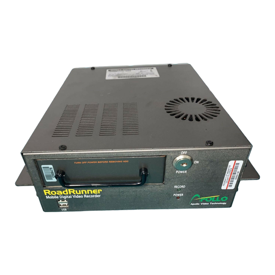
Mobile Digital Video Recorder Chapter 3 ─ Configuration NOTE: Your DVR should be completely installed before proceeding. Refer to Chapter 2 ─ Installation. Front Panel Controls Figure 7 ─ DVR front panel Power Switch: The unit can be turned on or off with the key provided with the unit. HDD LED: The LED flickers when the DVR is recording or searching video on the hard disk drive. -
Page 22: Premium Dcp Controls
User’s Manual Premium DCP Controls POWER: The LED is lit when the DVR is operational. REC: The LED is lit when the DVR is recording video, or flickers when the DVR is in the panic recording mode. 1 ~ 4 (Camera button): Pressing the button does multiple functions as follows. -
Page 23: Turning On The Power
Mobile Digital Video Recorder Turning on the Power The DVR can be turned on by inserting the key in the On/Off switch and rotating it clockwise. The switch can be left in the On position and the key removed. This way the DVR will power up when the ignition is turned. -
Page 24: Entering Setup Menu
User’s Manual Entering Setup Menu When the DVR turns on, the live monitoring screen appears. Clicking the right mouse button on the live monitoring screen displays the following live monitoring menu. Selecting Setup Menu… enters the setup screen. The Login screen appears. Figure 11 ─... -
Page 25: System Menu
Mobile Digital Video Recorder System Menu Figure 14 ─ System Menu Information Setup Select Information in the System menu and the Information screen appears. Figure 15 ─ Information screen Site: Name the site location using a virtual keyboard. System ID: Assign a System ID number to identify the unit when it is connected with other DVRs through the RS485 port. -
Page 26: Figure 16 ─ Upgrade Screen
User’s Manual Choose the desired upgrade file. Available upgrade package file names are listed in the drop-down list. The “.rui” indicates that the file is for software upgrades and “.ofi” indicates that the file is for optical drive firmware upgrades. Selecting Install will install the selected software package. -
Page 27: Date/Time Setup
Mobile Digital Video Recorder Recorded Data: Displays the time information of recorded data. Selecting Clear All Data… clears all video data. You will be asked to verify that you wish to clear all data before the DVR erases the video data. It will not clear the System Log. Date/Time Setup Select Date/Time in the System menu and the Date/Time setup screen appears. -
Page 28: Figure 21 ─ Holiday Setup Screen
User’s Manual Holiday Figure 21 ─ Holiday setup screen + : Add holidays. When selecting it, the current date appears. Select the month and day and change them by using the arrow buttons. : Delete holidays. NOTE: Holidays that do not fall on the same date each year should be updated once the current year’s holiday has passed. -
Page 29: Figure 23 ─ Storage Information Screen
Mobile Digital Video Recorder NOTE: You can use the domain name instead of IP address if you already set up the DNS Server when setting up the LAN. Storage Setup Select Storage in the System menu and the Storage setup screen appears. Information It displays information about the DVR’s storage devices. -
Page 30: User Setup
User’s Manual Status Figure 26 ─ Storage Status screen Type: Displays the type of storage device. Disk Bad: Displays the percentage of bad sectors. Not Formatted indicates the device is not formatted. Temperature: Displays the temperature of the storage device. S.M.A.R.T.: Displays “Good”, “Bad”... -
Page 31: Figure 28 ─ New Group Setup Screen
Mobile Digital Video Recorder It displays the authorized groups and users. You can add and delete groups and users. When adding a group, you can assign authority levels to the group. +/-: Indicates that the item is a Group Name. Select to collapse or expand the user groups. If there is a –... -
Page 32: Shutdown
User’s Manual Record Setup: The user can establish all Record settings on a local system or a PC running RAS. – Search: The user can access the Search mode on a local system or a PC running RAS. – Clip-Copy: The user can copy video clips on a local system or a PC running RAS, and save video data in –... -
Page 33: Network Menu
Mobile Digital Video Recorder Network Menu Figure 32 ─ Network Menu Network Setup Select Network in the Network menu and the Network setup screen appears. You will be able to change the Network, LAN, Modem and DVRNS settings. Network Figure 33 ─ Network setup screen Transfer Speed: Set the transfer speed by using the arrow buttons, and select the unit of measure for the transfer speed between: bps and ips. -
Page 34: Figure 34 ─ Lan Setup Screen
User’s Manual Figure 34 ─ LAN setup screen Type: Choose the type of network configuration from: Manual, DHCP and ADSL (with PPPoE). Manual: Select to set up LAN parameters manually. Adjust the numbers of the IP Address, – Gateway and Subnet Mask by using the arrow buttons. NOTE: You will need to get the appropriate IP Address, Gateway and Subnet Mask from your network administrator. -
Page 35: Figure 35 ─ Port Numbers Setup Screen
Mobile Digital Video Recorder Change the numbers by using the arrow buttons. The factory default Port settings are: Remote Admin: 8200 Remote Callback: 8201 Remote Watch: 8016 Remote Search: 10019 Figure 35 ─ Port Numbers setup screen NOTE: You will need to get the appropriate Port Numbers for each RAS related program (Admin, Callback, Watch and Search) from your network administrator. -
Page 36: Figure 37 ─ Dvrns Setup Screen
User’s Manual DVRNS Figure 37 ─ DVRNS setup screen NOTE: When LAN settings have been changed, set up the DVRNS after saving your LAN changes by selecting Save. Use DVR Name Service: Select to use DVR name service function. NOTE: The DVRNS (DVR Name Service) allows the DVR to use Dynamic IP addresses for remote connection. -
Page 37: Notification Setup
Mobile Digital Video Recorder CAUTION: If you want to use the same DVR name registered on the DVRNS server after initializing the system using the factory reset, you need to contact the DVRNS server manager. Please record and save the help desk information before factory reset. CAUTION: The DVRNS registration will be limited to one DVRNS server. -
Page 38: Configuring Devices
User’s Manual NOTE: You can use the domain name instead of IP address if you already set up the DNS Server when setting up the LAN. NOTE: The e-mail address must include the “@” character to be a valid address. Callback Figure 40 ─... -
Page 39: Camera Setup
Mobile Digital Video Recorder Camera Setup Select Camera in the Devices menu, and the Camera setup screen appears. Settings Figure 42 ─ Camera setup screen Title: Change the Title of each camera by using the virtual keyboard. Use: Determine which cameras will display on the monitors by selecting Normal, Covert 1 or Covert 2 from a drop-down list. -
Page 40: Audio Setup
User’s Manual Product: Choose a PTZ model, and a list of PTZ devices appears. Select your camera from the list. You will need to connect the camera to the RS232 or RS485 connector on the back of the DVR following the camera manufacturer’s instructions. -
Page 41: Alarm-Out Setup
Mobile Digital Video Recorder Alarm-Out Setup Select Alarm-Out in the Devices menu. The Alarm-Out screen allows you to change the settings and establish a schedule for each alarm output from the DVR. Settings Figure 47 ─ Alarm-Out Settings screen Title: Enter the title of each alarm output by using the virtual keyboard. Type: Set the alarm output for NO or NC (normally open or normally closed). -
Page 42: Display Setup
User’s Manual Channels: Choose which alarm outputs will be active. : Delete an alarm output schedule. You will be asked to confirm whether or not you really wish to delete the schedule. Display Setup Select Display in the Devices menu. The Display screen allows you to select what information will be displayed on the monitor. -
Page 43: Figure 50 ─ Osd Margin Screen
Mobile Digital Video Recorder You can adjust the horizontal and vertical margins so that text and icons will not be hidden beyond the edges of the monitor. Figure 50 ─ OSD Margin screen Main Monitor Figure 51 ─ Main Monitor screen You can adjust the display dwell time for each camera displayed on the main monitor. -
Page 44: Remote Control Setup
User’s Manual Remote Control Setup Select Remote Control in the Devices menu, and the Remote Control setup screen appears. You can select a port and make correct settings for a remote keyboard. Figure 52 ─ Remote Control setup screen Port: Choose from None, RS232 and RS485. Select Setup… to configure port’s setting for the device you are connecting to DVR (Baud Rate, Parity, Data Bits and Stop Bits). -
Page 45: Recording Settings
Mobile Digital Video Recorder NOTE: The GPS cannot be configured if the RS232 port and RS485 port are in use for PTZ control, networking, text input or remote keyboard. Enable Recording: Select to record images with GPS information. Use GPS Time Sync.: Select to synchronize the time to the GPS satellite in the interval of 1 hour. Speed Unit: Select the unit of measure for the display speed between km/h and mph when displaying GPS speed on the screen. -
Page 46: Schedule Setup
User’s Manual Event Record Dwell: Choose the length of time you would like to record for the associated event. Refer to Event Actions screen in this chapter for information regarding event recording. Auto Deletion: Adjust the length of time recorded data will be kept. The DVR automatically deletes video recorded earlier than the user-defined period under three conditions: at midnight, whenever the system reboots or whenever the user changes the Auto Deletion settings. -
Page 47: Pre-Event Setup
Mobile Digital Video Recorder Event: When the DVR is in the Event mode, the red icon displays at the top-left corner of the – screen. The DVR will record and displays the icon at the top-left corner of the screen when any event occurs. -
Page 48: Event Settings
User’s Manual Event Settings Your DVR can be set to detect many different events. You can also determine how it reacts to these events. Figure 59 ─ Event menu Alarm-In Setup Select Alarm-In in the Event menu, and the Alarm-In setup screen appears. Settings Figure 60 ─... -
Page 49: Figure 61 ─ Alarm-In Actions 1 Screen
Mobile Digital Video Recorder Actions 1 Figure 61 ─ Alarm-In Actions 1 screen You can set the actions the DVR will take whenever it senses an input on one of its alarm input connectors. No.: Indicates an alarm-in device number. Record: Choose cameras as many as you wish to be associated with the alarm-in device. -
Page 50: Motion Detection Setup
User’s Manual Actions 2 Figure 63 ─ Alarm-In Actions 2 screen PTZ: Choose the preset position for each PTZ camera, where you want PTZ cameras to move to whenever the DVR detects an input on the associated alarm input. Motion Detection Setup Select Motion Detection in the Event menu, and the Motion Detection setup screen appears. -
Page 51: Figure 66 ─ Motion Detection Zone Screen
Mobile Digital Video Recorder Zone: Define the area of the image where you want to detect motion; e.g., a doorway, and the Motion Detection Zone screen appears. The Motion Detection Zone screen is laid over the video for the selected camera. You can select or clear a block by clicking the mouse button to set up motion detection zones. -
Page 52: Figure 70 ─ Motion Detection Actions 1 Screen
User’s Manual Actions 1 Figure 70 ─ Motion Detection Actions 1 screen The DVR can be set to react to motion detection differently for each camera. NOTE: You can associate multiple cameras with a camera that detects motion. No.: Indicates a camera number. Record: Choose cameras as many as you wish to be associated with the camera. -
Page 53: Video Loss Setup
Mobile Digital Video Recorder Actions 2 Figure 71 ─ Motion Detection Actions 2 screen PTZ: Choose the preset position for each PTZ camera, where you want PTZ cameras to move to whenever the DVR detects motion on the selected camera’s input. Video Loss Setup Video Loss in the Event menu, and the Video Loss setup screen appears. -
Page 54: Figure 73 ─ Video Loss Actions 1 Screen
User’s Manual Actions 1 Figure 73 ─ Video Loss Actions 1 screen The DVR can be set to react to video loss differently for each camera. No.: Indicates a camera number. Record: Choose cameras as many as you wish to be associated with the camera. When the DVR detects video loss on the camera, it starts recording video from all the associated cameras. -
Page 55: Text-In Setup
Mobile Digital Video Recorder Actions 2 Figure 74 ─ Video Loss Actions 2 screen PTZ: Choose the preset position for each PTZ camera, where you want PTZ cameras to move to when the DVR detects video loss on the selected camera’s input. Text-In Setup Text-In in the Event menu, and the Text-In setup screen appears. -
Page 56: Figure 76 ─ Text-In Device Settings Screen
User’s Manual Figure 76 ─ Text-In Device Settings screen Port: Choose from None, RS232, RS485 and USB-Serial (1~8). Select Setup… to configure port’s setting for the device you are connecting to the DVR (Baud Rate, Parity, Data Bits and Stop Bits). Use the ATM or POS manufacturer’s recommended settings when configuring the RS232, RS485 or USB-Serial ports. -
Page 57: Figure 77 ─ Text-In Actions 1 Screen
Mobile Digital Video Recorder Actions 1 Figure 77 ─ Text-In Actions 1 screen The DVR can be set to react to text input. No.: Indicates a text-input device number. Record: Choose cameras as many as you wish to be associated with the text-input device. When the DVR detects a text input, it starts recording video from all the associated cameras. -
Page 58: System Event Setup
User’s Manual Actions 2 Figure 78 ─ Text-In Actions 2 screen PTZ: Choose the preset positions for each PTZ camera, where you want PTZ cameras to move to when the DVR detects text input. System Event Setup Select System Event in the Event menu, and the System Event setup screen appears. Health Check Figure 79 ─... -
Page 59: Figure 80 ─ Check Recording Screen
Mobile Digital Video Recorder Day: Choose the days that the DVR will run – self-diagnostics. Range: Set the time range that the DVR will run self- – diagnostics. Interval: Choose the time interval that the DVR will run – self-diagnostics. : Delete a check recording schedule. -
Page 60: Figure 83 ─ System Event Actions Screen
User’s Manual Enable: Select to run S.M.A.R.T. – NOTE: If Enable is turned Off, you will not be able to make changes to any of the boxes. Check Time: Choose the time interval from Monthly, Weekly and Daily. If you select Monthly, you –... -
Page 61: Event Status Setup
Mobile Digital Video Recorder Event Status Setup Select Event Status in the Event menu, and the Event Status screen appears. Event Status Figure 84 ─ Event Status screen The Event Status screen displays the status of the DVR’s systems and inputs. Events will be highlighted, and related channels or events will flicker for five seconds when detected. - Page 62 User’s Manual...
-
Page 63: Chapter 4 ─ Operation
Mobile Digital Video Recorder Chapter 4 ─ Operation NOTE: This chapter assumes your DVR has been installed and configured. If it has not, please refer to Chapters 2 and 3. The main functions of DVR are recording and playing back video. However, you have much greater control over recording and playing back video. -
Page 64: Display Menu
User’s Manual Display Menu Camera: Displays the selected camera full screen. When in the PIP display mode, clicking the right mouse button and selecting PIP changes the location and the size of the PIP. PIP: Select in the single-screen mode to enter PIP mode and a Picture-in-Picture displays. -
Page 65: Freeze Mode
Mobile Digital Video Recorder Freeze Mode Selecting Freeze enters the Freeze mode and freezes the current image on the screen. Selecting Freeze again exits the Freeze mode. While in the Freeze mode, the icon displays in bottom-left corner if Freeze is selected in the Display setup screen (OSD tab). Zoom Mode Selecting Zoom…... -
Page 66: Gps Information
User’s Manual You can save camera position settings as “presets” so that you can go directly to desired views. Once you have the camera at the Press the button on the PTZ desired settings, press the button toolbar to load the PTZ preset and the Preset View dialog box will on the PTZ toolbar, and the PTZ appear. -
Page 67: Recording Video
Mobile Digital Video Recorder Recording Video Once you have installed the DVR following the instructions in Chapter 2 ─ Installation, it is ready to record. The DVR will start recording based on the settings you made in the Record setup screen. See Chapter3 ─... -
Page 68: Searching Video
User’s Manual You can control playback by using the following playback toolbar displayed when positioning the mouse pointer on the playback screen. Figure 90 ─ Playback toolbar Clicking on the left side exits the toolbar. If you want to display the toolbar again, position the mouse pointer on the screen. -
Page 69: Calendar Search
Mobile Digital Video Recorder Calendar Search Days with recorded video display on the calendar with white numbers. A time bar displays at the bottom of the calendar. Hours in which video was recorded will be highlighted with blue. Once the time bar is highlighted, you can select the time. -
Page 70: Text-In Search
User’s Manual You can also narrow your event search by selecting Option… and setting up the new search condition. From: Select First to search from the first recorded image. When it is not selected, you can enter a specific Date and Time. To: Select Last to search until the last recorded image. -
Page 71: Motion Search
Mobile Digital Video Recorder You can also narrow your event search by selecting Option… and setting up the new search condition. From: Select First to search from the first recorded image. When it is not selected, you can enter a specific Date and Time. To: Select Last to search until the last recorded image. -
Page 72: Clip-Copy Screen
User’s Manual You can also narrow your event search by selecting Option… and setting up the new search condition From: Select First to search from the first recorded image. When it is not selected, you can enter a specific Date and Time. To: Select Last to search until the last recorded image. - Page 73 Mobile Digital Video Recorder From: Select First to search from the first recorded image. When it is not selected, you can enter a specific Date and Time. To: Select Last to search until the last recorded image. When it is not selected, you can enter a specific Date and Time.
- Page 74 User’s Manual...
-
Page 75: Appendix A ─ Power Conditioner
Mobile Digital Video Recorder Appendix A ─ Power Conditioner The power conditioner prevents the DVR from damage caused by a surge or a reverse voltage when the power supply does not meet the requirement (9 ~ 30VDC, 10A) during operation. Check the power supply status during the vehicle’s starting and operation before installing the DVR and install the power conditioner when there is any possibility that the power supply does not meet the requirement. -
Page 76: Appendix B ─ Usb Hard Disk Drive Preparation
User’s Manual Appendix B ─ USB Hard Disk Drive Preparation Preparing the USB-IDE hard disk drive in Windows 2000 NOTE: Preparing a USB-IDE hard disk drive under Windows XP is almost identical to Windows 2000. 1. Connect the USB-IDE hard disk drive to your computer using the USB Cable. 2. -
Page 77: Appendix C ─ Text-In Query Examples
Mobile Digital Video Recorder Appendix C ─ Text-In Query Examples Query Example I 123456789012345678901234567890123456789012345678901234567890 Item Unit price amount ================================================== Coke 2.20 | 1(s) | $ 2.20 Fanta 2.20 | 1(s) | $ 2.20 Hotdog 3.50 | 3(s) | $ 10.50 Pepsi 1.95 | 1(s) | $... -
Page 78: Query Example Ii
User’s Manual Query Example II 123456789012345678901234567890123456789012345678901234567890 Item Unit price amount ================================================== Coke 2.20 | 1(s) 2.20 Fanta 2.20 | 1(s) 2.20 Hotdog 3.50 | 3(s) 10.50 Pepsi 1.95 | 1(s) 1.95 ================================================== total : $ 16.85 Thank you~~ In the above text-in data, you can find that the comparison value is located at 17 (Unit price, $ mark will be ignored automatically), 28 (Qty) and 40... -
Page 79: Appendix D ─ Time Overlap
Mobile Digital Video Recorder Appendix D ─ Time Overlap If the DVR’s time and date have been reset to a time that is earlier than the existing recorded video, it is possible for the DVR to have more than one video stream in the same time range. In this case, you can search overlapping video streams individually by selecting a specific segment. -
Page 80: Appendix F ─ Connector Pin Outs
User’s Manual Appendix F ─ Connector Pin Outs I/O Connector Pin Outs 1 to 8 Alarm Inputs 1 to 8 Chassis Ground (6 connectors) Relay Alarm Outputs (Normally Closed) Relay Common Relay Alarm Outputs (Normally Open) Alarm Reset In PANIC Panic Recording VDC Outputs Chassis Ground (9 connectors) -
Page 81: Appendix H ─ Map Of Screens
Mobile Digital Video Recorder Appendix H ─ Map of Screens... -
Page 82: Appendix I ─ System Log Notices
User’s Manual Appendix I ─ System Log Notices Boot Up Remote Setup Change Auto Deletion Shutdown Remote Setup Fail Search Begin Restart Setup Imported Search End Upgrade Setup Import Failure Clip-Copy Begin Upgrade Fail Setup Exported Clip-Copy End Power Failure Setup Export Failure Clip-Copy Cancel Time Change... -
Page 83: Appendix K ─ Specifications
Mobile Digital Video Recorder Appendix K ─ Specifications VIDEO Signal Format NTSC or PAL (Auto Detect) Video Input Composite: 4 or 8 inputs, 1 Vp-p, auto-terminating, 75 Ohms Monitor Outputs Composite: 1 BNC, 1 Vp-p, 75 Ohms Composite: 720x480 (NTSC), 720x576 (PAL) Video Resolution VGA: 800x600 @ 60Hz Playback/Record Speed... - Page 84 WEEE (Waste Electrical & Electronic Equipment) Correct Disposal of This Product (Applicable in the European Union and other European countries with separate collection systems) This marking shown on the product or its literature, indicates that it should not be disposed with other household wastes at the end of its working life. To prevent possible harm to the environment or human health from uncontrolled waste disposal, please separate this from other types of wastes and recycle it responsibly to promote the sustainable reuse of material resources.
Need help?
Do you have a question about the RoadRunner MR8 Series and is the answer not in the manual?
Questions and answers