Table of Contents
Advertisement
Quick Links
Advertisement
Table of Contents

Related Manuals for Pocket NC V2-50DA

Summary of Contents for Pocket NC V2-50DA
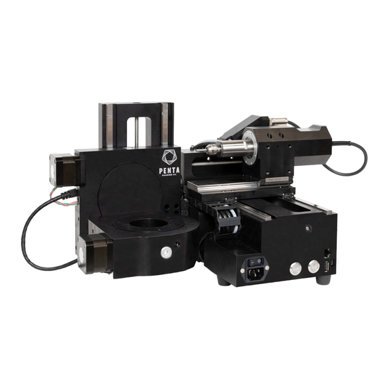
- Page 1 Getting Started with the Pocket NC V2-50DA...
-
Page 2: Table Of Contents
Revision History First Release: August 2019 (KN) Introduction Welcome to your Pocket NC V2-50DA. This tutorial goes over information on how to setup and run the Pocket NC V2-50DA for the first time. This includes: Removing the shipping bolts Installing the machine into the enclosure... -
Page 3: Safety
10 minutes. Do not interrupt the warm-up cycle and note that it will stop automatically. If the Warm-Up runs longer than the 50 minutes or 10 minutes expected please call support at Pocket NC, 1(406)451-3799. The warm-up cycles the speed of the spindle, increasing the RPM every few minutes. The main reason for the warm-up cycle is to evenly coat the bearings in the spindle with lubrication before cutting. -
Page 4: Getting Started
0:10 to 0:35 There are four shipping bolts installed in the Pocket NC in order to lock the axes in position and prevent damage to the machine during shipment. These bolts must be removed before the machine may be used. The bolts are M6x8x25 shoulder bolts. - Page 5 The other two shipping bolts are located on the X-carriage behind the spindle. They are both accessed from the top of the X-carriage.
-
Page 6: Enclosure Installation
Materials Needed: (5) M4x6 screws* (5) rubber bumpers (optional)* Pocket NC V2 Enclosure Pocket NC V2 Mill *Included in enclosure hardware kit Tools Needed... - Page 7 3) With the enclosure carefully overhanging a table or workbench as shown, start one of the M4x6 fasteners into the screw hole closest to the USB port using a 3mm hex key. 4) Rotate the machine so the chip tray opening is hanging off the table and install one of the M4x6 screws into the back of the machine.
- Page 8 5) Rotate the enclosure back to the first position and tighten the first screw. 6) Carefully place the enclosure on its back and fully open the lid to prevent it from opening on its own. 7) Install the 3 remaining screws. 8) Clean off the bottom of the enclosure and stick on the 5 rubber bumpers if desired.
-
Page 9: Connecting The Air Supply
0:47 to 1:26 Below is an example of the air setup required to run the Pocket NC V2-50. Please note that the source of air and inlet hose may differ. The user will need to supply and install the appropriate adapter into the ¼”... - Page 10 In the setup above, the air supply is a Gast air compressor with ¼” air hose (red) supplying air to the CKD filter and regulator that is included with the V2-50. The 4mm (black) hose supplies air to the tee on the backside of the spindle, which supplies air to the internal air sensor. The tee also carries the air to the spindle using a short length of 4mm hose connected to the blue connection on the end of the spindle motor.
-
Page 11: Installing Or Changing The Tool To Cut The Aligner
Installing or Changing the Tool to Cut the Aligner Corresponding video is here: h ttps://www.youtube.com/watch?v=vq8tZN9lZa4 from 1:14 to 1:28 1) Make sure the spindle is off (it can be hard to tell when running at low RPM’s) 2) Locate the lever on the spindle and pull it towards you until it clicks into the “Open” position. - Page 12 6. Once the driver is installed and the red LED is flashing open a browser (Chrome, Firefox or Safari) and go to 192.168.7.2. Note, internet explorer browser will not work. Note you are not connecting to the internet here you are connecting to the address of the machine, so you do not need an internet connection.
- Page 13 “E-Stop” button in the upper right corner of the screen. You will note that the E-stop (red button) on the Pocket NC mill will blink until the motor power is enabled and will be solid after the motors are active. The E-Stop button turns to red to indicate it’s on.
-
Page 14: Measuring Tool Offset (Telling The Machine Where The End Of The Tool Is)
10. Lastly, run the Warm-Up cycle, this will prepare the spindle to cut. If the machine has been off for more than 12 hours but less than 1 week it will run a 10 minute warm-up cycles. If the machine has been off for more than 1 week it will run a 50 minute warm-up cycle. Before running the cycle be sure that the tool is installed and secure (it is not good to run the machine without a tool installed in the spindle) and that the air is on. - Page 15 3) You will then see the tool table, as shown below. With the tool installed click the “Measure Tool 1” button in the right most column.
-
Page 16: Shutdown Of The Machine
❏ Navigating to the user interface ❏ Measuring the tool length offset ❏ Shutting down the machine properly The next in this series is How to Use the Pocket NC V2-50DA which covers the software and procedure for cutting down the dental aligner.
Need help?
Do you have a question about the V2-50DA and is the answer not in the manual?
Questions and answers