Advertisement
MA1-HH & MA1-PCB
Operations Guide
Midi Message Analyzer
PRODUCT OVERVIEW
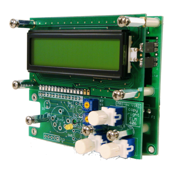
The MA1 is a fully input isolated midi signal analyzer. The MA1 module rec eives midi messages from
a keyboard, computer or any midi instruments or device, decodes and displays the messages. By
entering the "HOLD" mode, the last few messages can be viewed. This unit can be programmed for
many different functions and custom configurations . By ganging MA1's together, each one could be
programmed to filter out selected messages, and at a quick gla nce the latest information is displayed.
The MA1 has 2 receive modes of operation:
DECODE MODE
In the Decode mode the display shows the type of message , Channel number, and decimal
equivalent of the data. The 'Note' information can be viewed as the decoded note or as a note
number. Middle C can be changed from C3, C4, or C5. In the HOLD mode the last few bytes can be
displayed and scrolled through, including a message counter. Any message type can be filtered out.
An indicator shows if 'Midi Time Code' (F1), 'Time Clock' (F8), and 'Active Sensing (FE) messages
present whether they're filtered or not. System Exclusive messages are displayed with all the
associated bytes that can be scrolled through indepen dently too and displays a total byte count and
an individual byte counter.
HEX MODE
In the Hex mode the data is displayed in a Hexadecimal format for technical viewing, and displays
the data AS IS without any decoding. In the HOLD mode the last 112 bytes can be displayed and
scrolled through, including a byte counter. 'Midi Time Code' (F1), 'Time Clock' (F8), and 'Active
Sensing (FE) messages can be filtered out. An indicator shows if those messages are present
whether they're filtered or not.
The bottom right of the display shows errors, filter on/off, and if MTC, Timing clock and Active
Sensing are present. Both modes retain 112 bytes of data that allows the user to 'HOLD' and view by
scrolling left and right through the data.
ELM Video
Technology, Inc.
"Innovative DMX and MIDI Products"
www.elmvideotechnology.com
MA1_PCB_Operations_Guide B.lwp
copyright
©
ELM 2012-2016
Advertisement
Table of Contents

Summary of Contents for ELM Video MA1-HH
- Page 1 ELM Video MA1-HH & MA1-PCB Technology, Inc. Operations Guide “Innovative DMX and MIDI Products” Midi Message Analyzer PRODUCT OVERVIEW The MA1 is a fully input isolated midi signal analyzer. The MA1 module rec eives midi messages from a keyboard, computer or any midi instruments or device, decodes and displays the messages. By entering the “HOLD”...
- Page 2 SWITCH & CONNECTION OVERVIEW f - framing err Active sns t - timeout err Clock o - overrun err ? - unknown Filter on 6. DATA/HOLD - NORMAL operation indicates data is present, constant ON indicates ‘HOLD’ mode. 8. LCD - Liquid Crystal Display contrast adjustment. 9.
-
Page 3: Operation
Operation There are 2 modes of operation: PROGRAM and RECEIVE mode. In the receive mode there are 2 modes: DECODE and HEX, selected in the program mode. The module powers in a receive mode. Within these modes the last messages or bytes can be viewed by pressing the ‘hold’... -
Page 4: Decode Mode
DECODE MODE - The decode mode is selected in the program mode. Within the decode mode there is 2 modes of operation; Display and Hold mode. In the Display mode all incoming MIDI data will be decoded and displayed. Any or All message types can be programmed to be filtered out. -
Page 5: Hex Mode
HEX MODE - The hex mode is selected in the program mode. Within the decode mode there are 2 modes of operation; Display and Hold mode. In the Display mode all incoming MIDI data will be displayed in hexadecimal format. The newest byte of data will be displayed in the upper right of the display. -
Page 6: Troubleshooting
Troubleshooting PROBLEM CHECK Unit won’t power up verify proper switch connector settings & jumpers Switch turns off modules I don’t want turned off check power switch connections Switch doesn’t work check fuse and power connections Won’t receive data on local module verify data is being sent from source check the DIN/BUS software setting is correct make sure input switch on front panel is selected...

Need help?
Do you have a question about the MA1-HH and is the answer not in the manual?
Questions and answers