Table of Contents
Advertisement
Quick Links
Advertisement
Table of Contents

Related Manuals for ICD NeoGCP i7 PLUS+

Summary of Contents for ICD NeoGCP i7 PLUS+
- Page 1 NeoGCP i7 PLUS+ User’s Guide (Rev. N)
- Page 2 NeoGCP PLUS+ C A U T I O N 1. It is recommended to use RPM measurement method as MPU to prevent start motor damage when using Doosan engine. If RPM measurement method is frequency, oil pressure switch is set to not use, and voltage is not generated at engine CRANK-ON, the start motor may be damaged.
- Page 3 NeoGCP PLUS+ - This manual can be applied to NeoGCP i7 PLUS Ver. 5.05 and up. (Some functions 3.13 and up) - Contact us for old version manuals. Firmware Application Changes Version Manual Version 3.05a Rev. H - Protection setup change of OCR and OCGR (Constant, Inverse, Instant added) 3.06 Rev.
-
Page 4: Table Of Contents
NeoGCP PLUS+ Table of Contents 1. NeoGCP i7 ........................ 9 1.1. NeoGCP i7 ..........................9 1.2. Special Features ........................9 1.3. Product Image ........................9 1.4. Specification ........................9 2. Button usage and LED Lighting Status ..............10 2.1. Button usage ........................10 2.2. - Page 5 NeoGCP PLUS+ 5.10. Number [49] ~ Number [52] GEN CT U, V, W, N .............. 18 6. Operation Sequence ....................19 6.1. Control Function According to Operation Mode ..............19 6.2. Operation Order ........................ 19 6.3. Ready ..........................19 6.4. PRE-CRANK ........................
- Page 6 NeoGCP PLUS+ 7.13. GOVERNOR TYPE (GOV) ....................28 7.14. TEETH(FACTOR)(TEETH) ....................28 7.15. BREAKER TYPE (TYPE) ....................28 7.16. BREAKER AUX CHECK (AUX) .................... 29 7.17. BUTTON BEEP (BEEP) ..................... 29 7.18. ALARM HORN TIME (HORN) ..................... 29 7.19. BACK-LIGHT TIME (LIGHT) ....................29 7.20.
- Page 7 NeoGCP PLUS+ 9.14. BREAKER AUX ........................35 9.15. UVR SIGNAL ........................35 9.16. FIRE-RUN ........................36 9.17. BLOCK ..........................36 9.18. MANUAL .......................... 36 9.19. AUTO ..........................36 9.20. GEN START ........................37 9.21. GEN STOP ........................37 9.22. BREAKER CLOSE ......................37 9.23.
- Page 8 NeoGCP PLUS+ 10.12. S_GEN START ........................ 44 10.13. S_GEN RUNNING ......................44 10.14. S_BLOCK MODE, S_MANUAL MODE, S_AUTO MODE, S_FIRE-RUN ......... 44 10.15. S_ALL ALARM, S_WARNING, S_HEAVY FAULT, S_TRIP FAULT, S_STOP FAULT, S_SHUTDOWN FAULT ......................44 10.16. Alarm Status ........................44 10.17.
-
Page 9: Neogcp I7
NeoGCP PLUS+ 1. NeoGCP i7 1.1. NeoGCP i7 - Neo Generator Control Panel i7 (NeoGCP i7) is a digital type controller that uses microprocessor for single operating generators. 1.2. Special Features - Easy and simple to set generator with 192 × 64 graphic LCD display. - Built-in OVR, UVR, OCR, OCGR functions. -
Page 10: Button Usage And Led Lighting Status
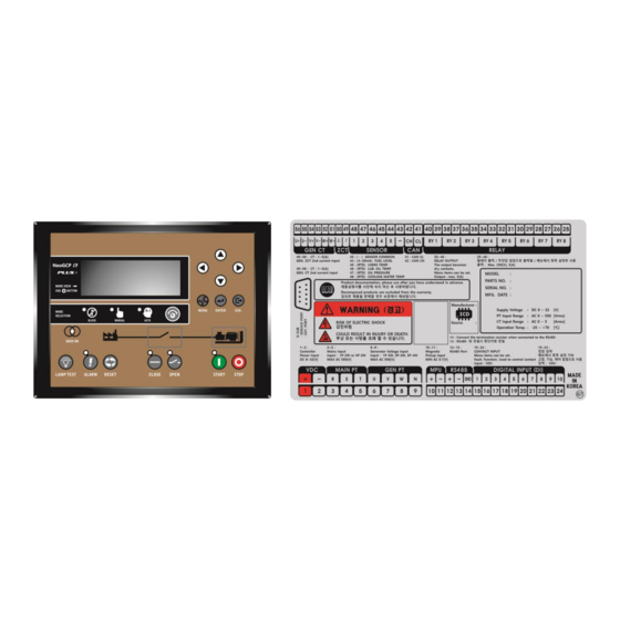
NeoGCP PLUS+ 2. Button usage and LED Lighting Status 2.1. Button usage - Adjustment and setup of various operation information possible with buttons on the front. ITEM DESCRIPTION - Use to select generator information on Main screen. DIRECTION - Use to move Menu on Menu screen. BUTTON - Use to move digits or change information on Menu screen. -
Page 11: Lcd Display Status
NeoGCP PLUS+ 3. LCD Display Status 3.1. Start Screen - When power is on, start screen will show product number and program version. 3.2. Main Screen - When program booting is completed from Start screen, it will switch to Main screen. - Main screen displays main information of Gen-set. -
Page 12: Alarm Screen
NeoGCP PLUS+ 3.3. Alarm Screen 3.3.1. Alarm check - In case of Alarm condition, screen will automatically switch to Alarm screen. - Number on the right of [ALARM MESSAGE] indicates number of times ALARM has occurred. - When multiple Alarm occurs, press [ALARM] button to check contents of ALARM in a sequence. 3.3.2. -
Page 13: Neogcp I7 Cable Specification And Size
NeoGCP PLUS+ 4. NeoGCP i7 Cable Specification and Size 4.1. NeoGCP i7 Cable Specification - All input and output of NeoGCP i7 implemented by pluggable terminal block. < Pluggable Terminal Block > - Cable specification as shown below, separation of low-current cables and high-current cables recommended to prevent noise. -
Page 14: Neogcp I7 Input And Output Port
NeoGCP PLUS+ 5. NeoGCP i7 Input and Output Port Item Description Item Description VDC+ Controller Power Input GEN CT U+ 8~32 [Vdc] VDC- Gen-set Current Input (CT 2 GEN CT U- MAIN R 0.01~10 [A], Max 10 [A], Peak 1 [s] Mains Voltage input GEN CT V+ 1P-3W : L1-52, N-49, L2-51... -
Page 15: Number [1], Number [2] Vdc
NeoGCP PLUS+ 5.1. Number [1], Number [2] Vdc ± - Number [1] and [2] ports supply power to 8~32 [Vdc]. - When power is supplied, there is a possibility of an inrush current depending on impedance of power supply. - To prevent damage from inrush current, overcurrent protection device such as a fuse or breaker is recommended to be connected in series with power cable. -
Page 16: Number[6] ~ Number[9]Gen Pt U, V, W, N
NeoGCP PLUS+ 5.3. Number [6] ~ Number [9]GEN PT U, V, W, N - Detects generator voltage of Max AC 550[Vrms] by Numbers [6] ~ [9] ports. - Wiring should be as follows. 1P-2W : L1-6, N-7 / 1P-3W : L1-6, N-7, L2-8 / 3P-3W : U-6, V-7, W-8 / 3P-4W : U-6, V-7, W-8, N-9 - If generator voltage exceeds AC 550[Vrms], user should use PT(Potential Transformer) and Voltage should not exceed AC 550[Vrms]. -
Page 17: Number [15] ~ Number [24] Di-Config
NeoGCP PLUS+ 5.6. Number [15] ~ Number [24] DI-CONFIG - When Vdc– is input through ports [15] - [24], corresponding signal will be as shown below. - For details of DI, refer to [DI 09 SET]. < DI Wiring Diagram > 5.7. -
Page 18: Number [47], Number [48] Gen Zct K, L
NeoGCP PLUS+ 5.9. Number [47], Number [48] GEN ZCT K, L - Detects Ground Current by ports [47], [48]. - Measurable minimum current 0.01[Arms], maximum current 10[Arms], and peak time 1[s]. - Change of setup needed according to type of ZCT(Video current transformer : Zero Current Transformer). -
Page 19: Operation Sequence
NeoGCP PLUS+ 6. Operation Sequence 6.1. Control Function According to Operation Mode. Functions BLOCK MANUAL AUTO FIRE LCD Screen [BLOCK] [MANUAL] [AUTO] [FIRE-RUN] BLOCK : ON BLOCK : OFF BLOCK : OFF BLOCK : OFF LED Indicator MANUAL : OFF MANUAL : ON MANUAL : OFF MANUAL : ON... -
Page 20: Pre-Crank
NeoGCP PLUS+ Conditions Menus that are influenced Description Should be 0 [RPM] Oil Press [0] and up: lower than set value [CONTROL] → [RUN-STATE OP-GAUGE] Sensor [0] : No check Oil Press [USE] : Should be Oil Press Low [CONTROL] → [[RUN-STATE OP-SWITCH] switch [NOT USE] :No check 6.4. -
Page 21: Idle Running
NeoGCP PLUS+ 6.6. IDLE RUNNING - If [IDLE STATUS] is being input or [IDLE TIME] is set, status will switch to [IDLE RUNNING]. - If [IDLE STATUS] is not being input, or [IDLE TIME] is 0, status will switch to [BUILD-UP]. - [C_IDLE SPEED] will output even during [CRANK-ON], [CRANK-CHECK]. -
Page 22: Stop
NeoGCP PLUS+ 6.10. STOP - [STOP], then switch to [READY]. - Check of stop status when using [PROTECTION] → [FAIL TO STOP]. - If RPM, Oil press sensor, Oil press switch are not in stop status until [STOP-HOLD TIME] reaches 0, [F_FAIL TO STOP] Alarm will output. -
Page 23: Scheduled-Run
NeoGCP PLUS+ - If [FIRE-RUN] is not input or [EM’CY STOP] is input or Shutdown Alarm occurs, Gen-set will stop and status will switch to the mode setup before [FIRE]. Menus that are influenced Setup Description [DI-CONFIG] → [EM’CY STOP] User setup [EM’CY STOP] input 6.14. - Page 24 NeoGCP PLUS+ < [AUTO] Mode Sequence Setup Example > - 24 - REV. N...
-
Page 25: System
NeoGCP PLUS+ 7. SYSTEM - Setup of basic information to run Gen-set. - Setup possible in stop mode. (Some menus excluded) Menu Description Setup POWER Input rated kW of GEN-SET 0 ~ 5000 [kW] Input Rated Frequency of GEN- FREQUENCY 40 ~ 60 [Hz] VOLTAGE Input Rated Voltage of GEN-SET... -
Page 26: Current (I)
NeoGCP PLUS+ 7.4. CURRENT (I) - Setup rated current of Gen-set. - Setup : 5 ~ 9999 [A] Rated Current Formula Rated Current[A] = Rated Output[kW] ÷ {1.732 × Rated Voltage[V] × 1000 × Power Factor(cosθ)} 7.5. GR CURRENT (GRI) - Setup ground current of Gen-set. -
Page 27: Ecu Type (Ep)
NeoGCP PLUS+ 7.8. ECU TYPE (EP) - NeoGCP g7 model with built-in CAN communication is recommended. - Setup : Not use, EMSS6, EDC7, Volvo-EMSS2, 16V Baudouin, FIAT, PERKINS, DN03 - Must use a separate CAN converter sold by our company when using ECU type. - If NeoGCP g7 model is used, the built-in CAN function can be used without a separate converter. -
Page 28: Ct Ratio (Ct)
NeoGCP PLUS+ Menus that are influenced Setup [SYSTEM] → [VOLTAGE] 6600 [V] [SYSTEM] → [PT RATIO] 60.0 (= 6600/110) 7.10. CT RATIO (CT) - Setup CT(Current Transformer) Ratio. - Setup : 5/5 ~ 9999/5 [A] 7.11. GR CT RATIO (ZCT) - Setup ZCT(Zero Current Transformer)Ratio. -
Page 29: Breaker Aux Check (Aux)
NeoGCP PLUS+ 7.15.2. START FAIL TRIP SET (TRIP) - Setup use / not use of breaker signal in case of start failure. - Setup : Use, Not use 7.16. BREAKER AUX CHECK (AUX) - Setup use / not use of breaker auxiliary contact. - Setup : Use, Not use 7.17. -
Page 30: Time Compensation (Clock)
NeoGCP PLUS+ 7.22. TIME COMPENSATION (CLOCK) - Adjust when time goes faster or slower. - Setup : -31 ~ +31 8. SENSOR-SET - Setup Sensor information needed in Gen-set run. - Setup possible in Stop mode. (Some menus excluded) Menu Description Setup COOLANT TEMP... -
Page 31: When Using Ep20
NeoGCP PLUS+ 8.4. When Using EP20 - When using EP20, press [▶] button to switch to Ext-Module sensor setup screen. Menu Description Factory Sensor Data Type EXT-MODULE SENSOR 1 DAEWOO Temp Sensor EXT-MODULE Not use, Coolant temp, Coolant (Recommended use of SENSOR 2 temp LH, Coolant temp RH, Oil temp sensor) -
Page 32: Di-Config
NeoGCP PLUS+ - VDO Press Sensor Setup Resistance Press 9. DI-CONFIG - Digital Input(DI) Setup. - When signal of user set type(N/O, N/C) is input, set message(TEXT) will output after set delay time(0.0 ~ 25.0) and then running mode of Gen-set will switch according to Alarm Level(7 level). - Setup possible in Stop mode. -
Page 33: User Fault
NeoGCP PLUS+ - When using EP20, additional contact input setup is possible as shown below. Menus that are influenced Setup Description [SYSTEM] → [EXT-MODULE] EP20 When using EP20 Oil Press S/W LH Oil Press S/W RH Relevant [DI-CONFIG] → From [DI 11 SET] Coolant S/W LH contact Coolant S/W RH... -
Page 34: Coolant Temp S/W
NeoGCP PLUS+ 9.5. COOLANT TEMP S/W - Used as coolant switch contact. - When contact is input, operation mode of Gen-set will switch according to set alarm level after set delay time. - If coolant high temp occurs in [BUILD-UP] or [RUN] or [COOLDOWN], then [F_COOLANT TEMP HIGH] Alarm will output. -
Page 35: Fail To Stop
NeoGCP PLUS+ 9.10. FAIL TO STOP - Used as stop failure contact. - When contact is input, operation mode of Gen-set will switch according to set warning level after set delay time. - Setup : TYPE(N/O, N/C), DELAY(0.0 ~ 25.0[s]), ALARM LEVEL(7level) 9.11. -
Page 36: Fire-Run
NeoGCP PLUS+ - When contact is input, Gen-set will start and when contact is not input, Gen-set will stop. - Setup : TYPE(N/O, N/C), Menus that are influenced Setup Description [CONTROL] → [MAINS SENSING] [UVR Contact] User set DI port [CONTROL] →... -
Page 37: Gen Start
NeoGCP PLUS+ 9.20. GEN START - Used as Gen-set start contact. - Gen-set will start when contact is input in [MANUAL], [READY]. - Gen-set will not stop even if contact is open after start. - Setup : TYPE(N/O, N/C), 9.21. GEN STOP - Used as Gen-set stop contact. -
Page 38: Alarm Reset
NeoGCP PLUS+ 9.24. ALARM RESET - Used as Alarm reset contact. - When Alarm occurs and is released, Alarm status will be initialized when signal is input. - When Alarm occurs and is not released, only Alarm Horn will be initialized when signal is input. - Setup : TYPE(N/O, N/C), 9.25. -
Page 39: Oil Press Rh S/W
NeoGCP PLUS+ 9.29. OIL PRESS S/W LH - Used as left oil press switch contact when using EP20. - [F_OIL PRESS LOW] will output when oil press low happens in [BUILD-UP], [RUN], [COOLDOWN]. - Setup : TYPE(N/O, N/C), DELAY(0.0 ~ 25.0[s]), ALARM LEVEL(7level) 9.30. -
Page 40: Do-Config
NeoGCP PLUS+ 10. DO-CONFIG - Digital Output(DO) Setup. - Setup possible in Stop mode. (Some items excluded) DO List Description DO List Description C_PRE-CRANK Pre-heat F_OVER VOLTAGE Over voltage C_CRANK Start motor F_UNDER VOLTAGE Under voltage C_GOVERNOR Solenoid F_OVER CURRENT Over current C_BREAKER CLOSE Breaker close... -
Page 41: C_Pre-Crank
NeoGCP PLUS+ - When using EP20, additional contact input setup possible as shown below. Menus that are influenced Setup Description [SYSTEM] → [EXT-MODULE] EP20-1 When using EP20-1 Relevant [DO-CONFIG] → From [DO 09 SET] C_AIR HEATER contact ※ Only applicable in EP20 10.1. -
Page 42: C_Governor
NeoGCP PLUS+ 10.3. C_GOVERNOR - Used as governor output contact. Menus that are influenced Setup Description Refer to picture [SYSTEM] → [RPM] → [GOVERNOR TYPE] FUEL, STOP shown below < [C_GOVERNOR] output according to operation status > 10.4. C_BREAKER CLOSE - Used as Breaker Close output contact in [RUN] when status is not BREAKER TRIP ALARM. -
Page 43: C_Alarm Buzzer
NeoGCP PLUS+ Menus that are influenced Setup Description [CONTROL] → [SCHEDULED-RUN] Setup scheduled-run [CONTROL] → [SCHEDULED-RUN]→ MANUAL, Setup scheduled-run ACB [SCHEDULED-RUN ACB CONTROL] AUTO control method [CONTROL] → [BREAKER TYPE] MCCB Use MCCB 10.6. C_ALARM BUZZER - Used as Alarm Buzzer output contact when Warning, Trip, Shut down occurs. - When Alarm occurs, contact will output during [ALARM HORN TIME], and when it is set as 0, Alarm Reset is only possible manually. -
Page 44: S_Mains On
NeoGCP PLUS+ 10.10. S_MAINS ON - Used as Mains On output. 10.11. S_MAINS OFF - Used as Mains off output. 10.12. S_GEN START - Used as Gen-set start output. < [S_GEN START] output according to status of Gen-set > 10.13. S_GEN RUNNING - Used as Gen-set running output. -
Page 45: Alarm Contacts1~10
NeoGCP PLUS+ - Setup of OVR, UVR, OCR, OCGR, OFR, UFR, OSR, USR, fail to start, fail to stop, fail to build-up, coolant temp high, coolant temp low, oil press high, oil press low, oil temp high, oil temp low, user temp high, user temp low, fuel level high, fuel level low, battery voltage high, battery voltage low. -
Page 46: Control
NeoGCP PLUS+ 11. CONTROL - Setup Gen-set operation status. Items Description Setup R-S, R-S-T , MAINS SENSING TYPE Setup Mains Sensing method AUTO-START Auto-Start delay time when Mains Off 0 ~ 7200 [s] DELAY AUTO-STOP DELAY Auto-Stop delay time when Mains On 0 ~ 7200 [s] TIME Setup voltage level to recognize as Mains... -
Page 47: Protection
NeoGCP PLUS+ Waiting time for RPM to fall within rated SVR DELAY 0 ~ 60 [s] range COOLDOWN TIME COOLDOWN Setup cooldown time in AUTO Mode 0 ~ 600 [s] STOP-HOLD TIME STOP Stop signal holding time 5 ~ 30 [s] Not use, [C_AIR HEATER] setup of use/not use and A/H INPUT TYPE... - Page 48 NeoGCP PLUS+ Items Description Setup Setup level for over voltage 100 ~ 150 [%] DELAY Setup constant delay time for over voltage 0.5 ~ 20.0 [s] LEVER Setup inverse lever for over voltage 0.05 ~ 1.0 INST Setup instant for over voltage Use, Not use ALARM Setup protection level for over voltage...
- Page 49 NeoGCP PLUS+ Items Description Setup HIGH Setup level for Coolant Temp High 0 ~ 150 [℃] COOLANT Setup protection level for Coolant Temp TEMP HIGH ALARM Refer to chart below High Setup level for Coolant Temp Low 0 ~ 150 [℃] COOLANT Setup protection level for Coolant Temp TEMP LOW...
-
Page 50: Serial Comm
NeoGCP PLUS+ 13. SERIAL COMM - NeoGCP i7 has 2 comm ports. - Setup of D-SUB 9pin is fixed as UART communication port. Items Description Setup UART ID Setup device ID for UART port UART BAUD BAUD Setup Baud Rate for UART port 9600 RATE UART PARITY... -
Page 51: Protection Test
NeoGCP PLUS+ 15. PROTECTION TEST - Test setup can be changed in [PROTECTION]. Items Description Setup OVER VOLTAGE TEST 200% of rated voltage at start-up UNDER VOLTAGE TEST OVER CURRENT TEST 200% of rated current at start-up OCGR TEST 200% of OCGR at start-up OVER SPEED TEST Change in [PROTECTION] OIL PRESS S/W TEST... -
Page 52: Engine Related Fault Items
NeoGCP PLUS+ ◎ 0[s] Always GEN BREAKER FAILURE When Breaker Close output occurs and then Breaker Aux contact is not input ※ ◎ : Fixed item ○ : Optional item 17.2. Engine Related Fault Items Alarm Level Delay Items Sequence applied Not use Warning Trip... -
Page 53: Sensor Related Fault Items
NeoGCP PLUS+ 17.3. Sensor Related Fault Items Alarm Level Delay Items Sequence applied Alarm Delay Sequence Alarm Delay Time Level Time applied Level Time 1[s] RUNNING ~ COOLANT TEMP ○ ○ ○ ○ ○ COOLDOWN HIGH Coolant Temperature detected higher than set value 1[s] RUNNING ~ ○... -
Page 54: Digital Input Related Fault
NeoGCP PLUS+ 17.4. Digital Input Related Fault Alarm Level Delay Items Sequence applied Alarm Delay Sequence Alarm Delay Time Level Time applied Level Time ○ ○ ○ ○ ○ Setup Always DI 1 USER When DI #1 is set as USER FAULT, USER FAULT(RUN), USER FAULT(STOP) FAULT input message will be displayed ○... - Page 55 NeoGCP PLUS+ - Setup of EXT-MODULE SENSOR alarm level and high/low value in [PROTECTION]. Alarm Level Delay Items Sequence Applied Time Warning Trip Stop Shutdown BUILD-UP ~ USER TEMP 2 ○ ○ ○ ○ ○ 2[s] COOLDOWN HIGH User Temperature 2 detected higher than set value BUILD-UP ~ ○...
- Page 56 NeoGCP PLUS+ Alarm Level Delay Items Sequence Applied Time Warning Trip Stop Shutdown RUNNING ~ USER PRESS 1 ○ ○ ○ ○ ○ COOLDOWN User Temperature 1 detected lower than set value ◎ Always USER PRESS 1 SENSOR User Pressure 1 sensor not connected RUNNING ~ ○...
-
Page 57: Comm Protocol- Modbus
NeoGCP PLUS+ 18. Comm Protocol- MODBUS 18.1. MODBUS PROTOCOL Items Setup Protocol Type MODBUS RTU Communication configuration RS485 Half Duplex Device ID Setup 0 ~ 255 Baud Rate Setup 9600, 19200, 38400 [bps] Parity Setup Even, Odd, None Data Bit 8 [bit] Stop Bit 1 [bit]... - Page 58 NeoGCP PLUS+ ADDRESS DATA TYPE SCALE BATTERY VOLTAGE [V] 16bit SIGNED INT RUNNING HOUR [hour] HIGH 16bit SIGNED INT Note1) RUNNING HOUR [hour] HIGH 16bit SIGNED INT Note1) kW HOUR [kWh] HIGH 16bit SIGNED INT Note2) kW HOUR [kWh] LOW 16bit SIGNED INT Note2) kvar HOUR [kvarh] HIGH...
- Page 59 NeoGCP PLUS+ Note5 ) BIT FIELD COOLANT DI 11 Input DI 1 User Fault TEMP HIGH Fault COOLANT DI 2 Input DI 12 Input TEMP LOW Fault Fault EMERGENCY OIL PRESS DI 3 Input DI 13 Input OCR (INSTANT) STOP HIGH Fault Fault...
- Page 60 NeoGCP PLUS+ Note6 ) BIT FIELD USER TEMP SENSOR 2 HIGH USER TEMP 2 SENSOR FAULT USER TEMP SENSOR 2 LOW COOLANT TEMP LH SENSOR FAULT COOLANT TEMP LH HIGH COOLANT TEMP RH SENSOR FAULT COOLANT TEMP LH LOW OIL PRESS LH SENSOR FAULT COOLANT TEMP RH HIGH OIL PRESS RH SENSOR FAULT COOLANT TEMP RH LOW...
-
Page 61: Gimac-Ii Plus Protocol
NeoGCP PLUS+ 18.2. GIMAC-II Plus PROTOCOL Items Setup Protocol Type MODBUS RTU Communication Configuration RS485 Half Duplex Device ID Setup 0 ~ 255 Baud Rate Setup 9600, 19200, 38400 [bps] Parity Setup Even, Odd, None Data Bit 8 [bit] Stop Bit 1 [bit] Support Function Code Request(04h) only... - Page 62 NeoGCP PLUS+ Note6) BIT FIELD Gen-set start Auto Mode OCGR Breaker open Output Breaker close Coolant Temp High output Breaker open Oil Press Low contact input Fail to Start, Fail to Breaker close Stop contact input Sys Error – Breaker aux alarm, Low battery DI 3 Input Alarm DO 1 Output voltage...
-
Page 63: Inverse Characteristics Curve
NeoGCP PLUS+ 19. Inverse Characteristics Curve - Applicable range : OVR, OCR, OCGR - X axis : Input value / Setup value - Y axis : Running time(s) - Lever setup value : 0.05~1.00 - Equation for trip time, - 63 - REV.
Need help?
Do you have a question about the NeoGCP i7 PLUS+ and is the answer not in the manual?
Questions and answers