
Summary of Contents for Georg Fischer Piping Systems MSA 340
- Page 1 GEORG FISCHER PIPING SYSTEMS MSA 340 Polyvalent Electrofusion Units Instruction Manual GEORG FISCHER CENTRAL PLASTICS...
-
Page 2: Table Of Contents
TABLE OF CONTENTS GENERAL INFORMATION WARNING NOTICE OTHER SYMBOLS AND NOTICES ABBREVIATIONS 1. INTRODUCTION 1.1 PRODUCT DESCRIPTION 1.2 COMPONENTS DESCRIPTION 1.2.1 Operation Controls 1.2.2 Display 1.2.3 Emergency Stop Switch 1.2.4 Ambient Temperature Sensor 1.2.5 USB Interface 1.2.6 Power Cable 1.2.7 Fusion Cables 1.3 BARCODE WAND OR BARCODE SCANNER 2. - Page 3 3. CONFIGURATION SETTINGS 3.1 LANGUAGE 3.2 DATE/TIME SETTING 3.3 FUSION PREPARATION 3.4 SERVICE MODE 3.5 TRACEABILITY 3.6 OPERATOR / JOB NUMBER 3.6.1 Operator 3.6.2 Job Number 3.7 MEMORY MANAGEMENT 3.8 TEMPERATURE UNIT 3.9 CENTRAL PLASTICS (CP) MODE 3.10 MANUAL MODE OPERATION 3.11 SHORT CIRCUIT 3.12 RESIST.
-
Page 4: General Information
GENERAL INFORMATION To allow an easy understanding of the manual and point out the duties of the operator, symbols are frequently used. The following tables contain the explanation of all symbols used in this manual. WARNING NOTICE Warning notices are used in this manual to inform the user about possible injuries or damage to properties. -
Page 5: Abbreviations
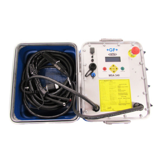
ABBREVIATIONS Symbol Meaning Polyethylene Pipe outer diameter (nominal) Adobe® Portable Document format Comma Separated Values format 1. INTRODUCTION The electrofusion MSA processor is designed according to current technology standards. Using it for purposes other than those described in this manual may cause injury to the operator or to others and could also damage the processor and/or other equipment. -
Page 6: Product Description
LCD display, guides the operator to successfully execute all the necessary operations. The MSA 340 has GPS capability and stores up to 1000 fusions that can be transferred to a PC via USB memory stick, in either PDF or CSV formats. -
Page 7: Display
Button Description Moves the cursor to previous field, increases set (▲) values, scrolls up. Moves the cursor to next field, decrease set (▼) values, scrolls down. Moves the cursor to the left. (◄) Moves the cursor to the right. (►) Enters into CONFIGURATION menus (DATA MENU RETRIEVAL or SET UP menu). -
Page 8: Ambient Temperature Sensor
1.2.4 Ambient Temperature Sensor This sensor measures the ambient temperature, to verify the temperature is in the permitted range (between -10° F and +120° F). It is located near the end of the fusion cables in the barcode din connector. The temperature sensor does not respond immediately to thermal changes. -
Page 9: Barcode Wand Or Barcode Scanner
The fusion cables come with 4.7mm (replaceable) tip connectors. • 3.0mm tip adapters will be available free of charge for customers who might still have some of the old style 3-pin connector type Central Plastic fittings on hand. • 4.0mm tip-adapters are available for purchase if required. 1.3 BARCODE WAND OR BARCODE SCANNER Using the barcode wand or scanner enables a quick insertion of fusion... -
Page 10: Fusion Process
2. FUSION PROCESS 2.1 OVERVIEW OF OPERATING PROCEDURE A standard fusion workflow is shown below:... -
Page 11: Switching On
2.2 SWITCHING ON Attention: Before connecting the machine to a power source, the operator must read ‘Technical Characteristics‘ Section 7! Caution: Check the voltage! The generator has to be started and allowed to run at full throttle before connecting the MSA unit and it must supply a constant output voltage! Any sudden changes could compromise the fusion and/or damage the processor. -
Page 12: Connect Fitting
If the job number function is active and the user wants to bypass this screen without entering any information, press the (►) button and then the START/OK (I) button to proceed. 2.4 CONNECT FITTING At this point, the display shows the ambient temperature, the date/time, the voltage and frequency values of the input supply voltage. -
Page 13: Cp Mode
carefully prepared: pipes shall be scraped, cleaned and aligned using a clamping tool. 2.5.1 CP Mode The processor program is designed to search for the CP mode connection first. To perform this task, the MSA processor tries first to work in CP mode, by reading the implanted resistors, according to ISO 13950. -
Page 14: Barcode Insertion
of options available to enter the required data as shown below: 2.5.2 Barcode Insertion The user can acquire the fusion parameters by scanning the barcode label with the barcode wand when the following is displayed: If the data cannot be read with the barcode wand for any reason, the user can manually enter the 24 digits printed on the barcode by pressing the (►) button to go into “edit”... -
Page 15: Manual Insertion
fusion parameters as seen below: If the data is correct, push START/OK (I). The processor will then compare the measured fitting resistance with the nominal value embedded in the barcode, and if there is not a conflict in resistance values, the processor will start the fusion process. If the value of the fitting resistance doesn’t match with the barcode data, the display shows an error message. -
Page 16: Process Incomplete Pre-Alert
the display. Enabling the manual mode allows the operator to input the fusion voltage and time using the membrane keypad as explained above: Using (▲)(▼), set the fusion Voltage and push START/OK (I) to confirm the entered voltage and move to the next field. Next, use (▲)(▼) and (◄)(►) to set the Fusion Time. -
Page 17: Fusion Preparation
NOTE: When the processor’s internal temperature is above 190°F, it will not allow a fusion to start and the following message will be displayed. At this point, it will be necessary to allow the processor to cool down before a fusion can be attempted. 2.7 FUSION PREPARATION To use the FUSION PREPARATION function, this... - Page 18 • Optional—user can enter data or simply press the START/OK (I) button to bypass and proceed • Required---user must enter traceability data to proceed (this format exclusively uses the European ISO barcode format only) • NO ISO---is a “free text” format that allows the customer to enter any data they choose using the arrow keys on the membrane or scanning a barcode (using Code 128 format) •...
-
Page 19: Gps
2.9 GPS The MSA 340 is equipped with a GPS (Global Positioning System) receiver, and allows for visualization and storage of the geographical coordinates (latitude, longitude) of the fusion location. The acquisition of the coordinates is done just before starting the fusion process. - Page 20 Once the GPS signal Icon is present, you can view the actual coordinates by pushing the (▲) button. The display will show the latitude, longitude, altitude of the current location. Press the STOP/ESC (O) to go back to the “Connect Fitting” screen.
-
Page 21: Hdop
2.9.1 HDOP HDOP (Horizontal Dilution of Precision) selects the best positional precision based on wider angular separation between the satellites used to calculate a GPS unit’s position. This parameter is influenced by obstructions such as nearby mountains or buildings. The possible values the user can select are: Values <... -
Page 22: Satellites In View
The user can choose to receive only signals which are tagged as DGPS (when ‘ENABLED’ is selected) to get more accurate GPS coordinates, but at this time this is only an advantage in areas that have the ground based stations in place. When the DGPS Mode is ‘Enabled’, the processor stops receiving signals from the orbital satellites to prevent interference with the ground based signals. -
Page 23: Fusion Process
There are 2 options available to the user: Values IMMEDIATE AVERAGE Immediate: What you get on the display is what the GPS sees at that time. In this case the data samples obtained are not manipulated, meaning that possible errors are not filtered out. These coordinates may not be as accurate as those calculated using the “Average”... - Page 24 NOTE: The MSA processor adjusts the fusion time according to the external temperature with temperature compensated fittings. Therefore, the final fusion time values might be slightly different from the nominal values captured from the barcode. During the first 10-15 seconds of the fusion, the machine checks the quality of the input voltage.
-
Page 25: Cooling Time
the fusion. This data will be part of the fusion protocol stored into the processor’s memory. 2.10.2 Cooling Time After the completion of the fusion process, the protocol summary and the remaining cooling time, if contained in the barcode, are displayed alternately. -
Page 26: Configuration Settings
3. CONFIGURATION SETTINGS To enter into the configuration menu, press the MENU button and select “MACHINE SETUP” using the (▲)(▼) buttons and push START/OK (I). The (▲)(▼)buttons allow the user to navigate all the machine settings, to scroll to a specific menu, and to make changes to the corresponding setting . -
Page 27: Date/Time Setting
Select the desired language by using the (▲)(▼) buttons and pushing START/OK (I) to confirm the setting. To cancel the operation press STOP/ESC (O). 3.2 DATE/TIME SETTING The DATE/TIME menu allows the user to set the calendar; date and time are shown in the format: Month/ Day/ Year Hour : Minutes... -
Page 28: Traceability
3.5 TRACEABILITY The TRACEABILITY menu defines the way the traceability data is considered during the fusion process: • Disabled: During the fusion initiation process, the machine will not ask for data to be entered (the related menu will not appear in the process sequence). •... -
Page 29: Job Number
• OPT: Data may be entered or skipped, depending on availability of the information and user preference using the keypad or by scanning a barcode (Interleaved 2/5 format). • NO: During the fusion process sequence, the machine will not ask for operator identity (the related menu will not appear in the process sequence). -
Page 30: Temperature Unit
• REMINDER: When there is room for less than 50 fusions to be stored in the internal memory, a message will be displayed at the beginning of each fusion cycle to alert the user that if the stored memory is important, it needs to be exported. If the user ignores these messages and does not export the data, the processor will assume that the data is not relevant and erase all the stored data once the memory is full. -
Page 31: Manual Mode Operation
“Bar-code” or “Manual” modes. Select to enable or disable this mode by using the (▲)(▼) buttons and pushing START/OK (I) to confirm the setting. To cancel the operation press STOP/ESC (O). 3.10 MANUAL MODE OPERATION The user can choose to Enable or Disable the ability of the MSA processor to operate in “Manual”... -
Page 32: Resist. Tolerance
This setting can be adjusted from 5% to 20%, but should remain at the pre-set factory setting of 20%. If the user feels this setting needs to be adjusted, they should discuss this with an authorized GF Central Plastics representative first. Select the desired short circuit value by using the (▲)(▼) buttons and pushing START/OK (I) to confirm the setting. - Page 33 • The Processor’s Serial Number • Job Number • Operator Identity • Date/Time of Fusion Cycle • Calibration Expired (Yes or No) • Calibration Due Date • Fusion Cycle Number • Error Number • Fitting Manufacturer • Ambient Temperature • Primary Voltage Min/Max •...
-
Page 34: View Fusion
The options available depend on user permission: a user in possession of the service password can access all the menus, while a standard user can only browse the existing protocols (cannot delete the fusions without the service mode password). 4.1 VIEW FUSIONS VIEW FUSIONS shows the basic information of the stored fusion data on the display. -
Page 35: Delete Fusion
Attention: A message asking to overwrite the file will appear if the memory stick already contains a file with the same name and extension. By Pressing START/OK (I), the old data will be overwritten and the newest data stored. Wait until the message “EXPORT IN PROGRESS” disappears, then you can extract the USB memory stick from the processor, and connect the memory stick to a PC for data upload. - Page 36 The error message appears on the display in the following format: The following table summarizes all the messages managed by the processor, with a brief explanation of the possible causes. DISPLAY INDICATION COMMENT AMBIENT TEMP TOO LOW Temp sensor detected a value below set limit.
-
Page 37: Fitting Coding
6. FITTING CODING In the table below are the symbols used to identify the fitting type. This is useful for manual data entry. Symbol Description Elbow 45° - 90° Tee 90° Single socket Coupler Tapping Tee Reducer < Electro-thermo-retractable sleeve... -
Page 38: Technical Characteristics
7. TECHNICAL CHARACTERISTICS Input Voltage and Frequency 115 V (+/-20%) 50 – 70 Hz 230 V (+/-20%) 50 – 70 Hz Suggested Generator Power 6kVA All fittings including 26” IPS Requirements / 660 mm couplings 3.5KVA Couplings up to 8”/ 225 mm, all reducers, and all saddles (service tapping tees, high volume tapping tees, &... -
Page 39: Standards
7.1 STANDARDS • ISO 12176-2 • ISO 12176-3 • ISO 12176-4 • EN 60335-1 (Safety) • EN 61000-6-2 (EMC) • EN 61000-6-4 and others (EMC) • CSA Certified 8. ENVIRONMENT CONDITIONS 8.1 WEATHER CONDITIONS Cold weather affects both fittings and equipment. Electrofusion fittings require the most energy at the beginning of the fusion cycle. -
Page 40: Utility Power
8.2.1 Utility Power Utility power is a reliable and ideal source of energy for the MSA electrofusion processor, however, it is not practical to access such a source in most field applications. When fusing with utility power, a dedicated connection to the service panel is recommended, since the potential amperage draw is very high. -
Page 41: Maintenance
Cord Length Wire Gauge 25 ft. # 10/3 (6 mm2) 50 ft. # 8/3 (10 mm2) Extension cords should not be used on 12 IPS & larger couplers. A pigtail is an adapter for converting from a 30 amp twist-lock to a 15 amp straight blade plug. -
Page 42: Fusion Cables
9.2 FUSION CABLES Regular inspection of the fusion cables is necessary. Damaged cables must be repaired or replaced. 9.3 FUNCTION CHECK-UP Regular updates and maintenance are required for the MSA processor (recommended maintenance is every 2 years). 9.4 PROCESSOR REPAIR If repairs are necessary, please contact your local representative. -
Page 43: Working With Safety In Mind
9.6 WORKING WITH SAFETY IN MIND “Make your contribution to safety in the workplace.” • Report any deviations from normal operation immediately to the responsible person. • Always keep safety in mind while working. 9.7 OTHER DISPOSAL Separate collection of electronic and electrical waste (as part of the equipment) has to be ensured through appropriate systems. - Page 45 For more information, please contact: GEORG FISCHER CENTRAL PLASTICS 39605 Independence, Shawnee, OK 74804 (800) 654-3872 (800) 733-5993 fax GFCentralMarketing@georgfischer.com www.gfcp.com / www.gfpiping.com Manual 10011440 (July 2017) GEORG FISCHER GEORG FISCHER CENTRAL PLASTICS PIPING SYSTEMS...
Need help?
Do you have a question about the MSA 340 and is the answer not in the manual?
Questions and answers