Table of Contents
Advertisement
Quick Links
Advertisement
Table of Contents

Related Manuals for NELSEN WATER NRO ROC2

Summary of Contents for NELSEN WATER NRO ROC2
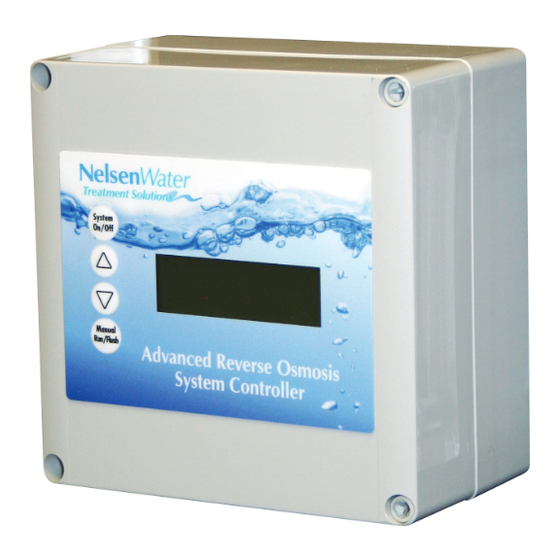
- Page 1 Nelsen NRO ROC2 System Controller Documentation...
-
Page 2: Table Of Contents
Table of Contents Description Page ..................................................................Specifications, Table 1 ............................................................Schematic, Figure 1 .............................................................. Controller Overview, Figure 2 ....................................................... Controller Detail: CPU-3 ..........................................................Controller Detail: TB-1 ............................................................Conductivity Probe Installation, Figure 5 ................................................Installation Instructions ........................................................... Controller Programming: Accessing Hidden Menus, Figure 6 .................................. -
Page 3: Specifications, Table 1
Table 1 - Specifications Inputs Tank level switches (2) Normally-Closed. Can be used with a single level switch. Inlet pressure switch Normally-Open. Pretreat lockout switch Normally-Open. Controller Power 120/240 VAC, 60/50Hz (Range: 90-145 VAC at 120 VAC setting, 180-290 VAC at 240 VAC setting Permeate Conductivity 0-1125 PPM, 0-2250 μs (standard sensor, CP-1, K=0.75) 0-1950 PPM, 0-3900 μs (optional sensor, CP-1H, K=1.3) -
Page 4: Schematic, Figure 1
Figure 1 - Simplified Schematic Figure 1. Simplified Schematic... -
Page 5: Controller Overview, Figure 2
Figure 2 - Controller Overview Keypad Display (4 line, 20 character) System ON/OFF, Clear, concise feedback Up Arrow on the RO’s status. Down Arrow Alarm Display backlight Manual Run, Manual Flush flashes along with audible beeper to indicate alarm condition. CPU Board CPU Board Conductivity Probe... -
Page 6: Controller Detail: Cpu-3
Figure 3 - Controller Detail: CPU-3 Typical Configuration Cable to Terminal Board Permeate Conductivity Probe Typical Configuration Main interface port. Connects via ribbon cable to Terminal Board. Sel-1 and Sel-2 Jumpers. Special purpose jumpers. Conductivity TDS Probe 1 TDS Probe 2 Programing Port (used with optional programming interface) See Appendix B (Optional Feed... -
Page 7: Controller Detail
Figure 4 - Controller Detail: Terminal Board, TB-1 (See Fig. 1 for schematic) Pump LED Illuminates when the Inlet Power Switch motor relay is energized. F2 Controller Power Fuse 120 VAC Feed and Flush F3 Solenoid Solenoid LEDs Power Fuse Transformer Illuminate when the relay is... -
Page 8: Conductivity Probe Installation, Figure 5
Figure 5 - Conductivity Probe Installation Install the Conductivity Probe in the “Run” of a Tee or equivalent location. Orient the Conductivity probe so that air can not become trapped in Probe the area near the probe. FLOW Installation 1 Drill the enclosure as needed and install liquid- 7 Connect the conductivity cell to the terminals on tight fittings for the wiring. -
Page 9: Controller Programming: Accessing Hidden Menus, Figure 6
Figure 6 - Controller Programming: Accessing the Hidden Menus 1 With the System ON, Press and Hold the Up and Down Arrows. 2 With the Up and Down Arrows depressed, Press the System On/Off button. The menu will switch to the RO Presets menu shown in Figure 7. -
Page 10: Controller Programming: Program Selections, Table 2
Table 2 - Controller Programming: ROC-2 Program Selections The controller has 4 separate, field-selectable sets of settings for configuring the RO. The factory default settings are shown below. The settings are identical except for variations in the flush behavior. • Program 1, High Pressure flush •... -
Page 11: Controller Programming: Menu Navigation, Figure 7
Figure 7 - Controller Programming: Menu Navigation VALUES RO Presets Program 1 RO Presets Program 1, 2, 3, 4 for other menus to change setting Manual=Edit Sys=Save Manual=Edit Sys=Save System Manual System Manual Save- Return to RO Display On/Off Run/Flush On/Off Run/Flush VALUES... -
Page 12: Controller Programming: Parameters Explained
Appendix A - Controller Programming: Parameters Explained Parameter Value Range Example Input Switch Behaviors Tank Level Switch delay (actuation and de-actuation) Seconds This specifies the time that the tank switch must be closed or open before the controller accepts it as a valid condition. -
Page 13: Controller Fault Displays
Appendix A - Controller Programming: Parameters Explained (cont.) Flush Behavior Value Range Example Time from last flush before Flush on Shutdown Minutes Minimum operation before Flush on Shutdown Minutes Flush duration on Shutdown Seconds Periodic Flush interval Minutes Periodic Flush duration Seconds Unit Idle Flush interval * Minutes... - Page 14 Controller Fault Condition Displays Permeate Conductivity Fault: (Permeate conductivity is higher than the alarm set-point.) Line 1 “Service Fault” Line 2 “Permeate TDS xxx ppm” or “Permeate Cond xxx uS” Line 3 “Alarm SP xxx ppm” or “Alarm SP xxx uS” Line 4 “To Reset Push OFF/ON”...
-
Page 15: Controller Programming: Programming Interface Overview
Appendix B - Controller Programming: Programming Interface Overview The ROC programming interface is a Windows-based tool for making changes to the ROC software. The program combines a simulator for testing your changes on the PC and an communications/programming interface for loading the software into the controller. -
Page 16: Warranty
Appendix C - Controller Limited Warranty What the warranty covers: The ROC 2 is warranted to be free from defects in materials and workmanship during the warranty period. If a product proves to be defective during the warranty period, Nelsen Corporation will at it’s sole option repair or replace the product with a like product.
Need help?
Do you have a question about the NRO ROC2 and is the answer not in the manual?
Questions and answers