Table of Contents
Advertisement
OPERATOR'S
MANUAL
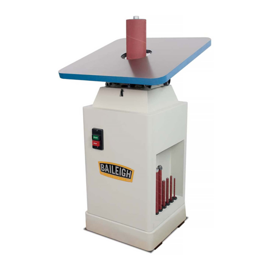
OSCILLATING VERTICAL
SPINDLE SANDER
MODEL: OS-2424
Baileigh Industrial, Inc.
P.O. Box 531
Manitowoc, WI 54221-0531
Phone: 920.684.4990
Fax: 920.684.3944
sales@baileigh.com
REPRODUCTION OF THIS MANUAL IN ANY FORM WITHOUT WRITTEN APPROVAL OF BAILEIGH INDUSTRIAL, INC.
IS PROHIBITED. Baileigh Industrial, Inc. does not assume and hereby disclaims any liability for any damage or loss
caused by an omission or error in this Operator's Manual, resulting from accident, negligence, or other occurrence.
Rev. 08/2015
© 2015 Baileigh Industrial, Inc.
Advertisement
Table of Contents

Related Manuals for Baileigh OS-2424


Summary of Contents for Baileigh OS-2424
- Page 1 REPRODUCTION OF THIS MANUAL IN ANY FORM WITHOUT WRITTEN APPROVAL OF BAILEIGH INDUSTRIAL, INC. IS PROHIBITED. Baileigh Industrial, Inc. does not assume and hereby disclaims any liability for any damage or loss caused by an omission or error in this Operator’s Manual, resulting from accident, negligence, or other occurrence.
-
Page 2: Table Of Contents
Table of Contents THANK YOU & WARRANTY ..................1 INTRODUCTION ......................3 GENERAL NOTES......................3 SAFETY INSTRUCTIONS ....................4 SAFETY PRECAUTIONS ....................7 TECHNICAL SPECIFICATIONS ................... 10 TECHNICAL SUPPORT ....................10 UNPACKING AND CHECKING CONTENTS ..............11 Cleaning ........................11 TRANSPORTING AND LIFTING .................. -
Page 3: Thank You & Warranty
THANK YOU & WARRANTY Thank you for your purchase of a machine from Baileigh Industrial. We hope that you find it productive and useful to you for a long time to come. Inspection & Acceptance. Buyer shall inspect all Goods within ten (10) days after receipt thereof. Buyer’s payment shall constitute final acceptance of the Goods and shall act as a waiver of the Buyer’s rights to inspect or... - Page 4 Baileigh Industrial makes every effort to ensure that our posted specifications, images, pricing and product availability are as correct and timely as possible. We apologize for any discrepancies that may occur. Baileigh Industrial reserves the right to make any and all changes deemed necessary in the course of business including but not limited to pricing, product specifications, quantities, and product availability.
-
Page 5: Introduction
After receiving your equipment remove the protective container. Do a complete visual inspection, and if damage is noted, photograph it for insurance claims and contact your carrier at once, requesting inspection. Also contact Baileigh Industrial and inform them of the unexpected occurrence. Temporarily suspend installation. -
Page 6: Safety Instructions
IMPORTANT PLEASE READ THIS OPERATORS MANUAL CAREFULLY It contains important safety information, instructions, and necessary operating procedures. The continual observance of these procedures will help increase your production and extend the life of the equipment. SAFETY INSTRUCTIONS LEARN TO RECOGNIZE SAFETY INFORMATION This is the safety alert symbol. - Page 7 SAVE THESE INSTRUCTIONS. Refer to them often and use them to instruct others. PROTECT EYES Wear safety glasses or suitable eye protection when working on or around machinery. PROTECT AGAINST NOISE Prolonged exposure to loud noise can cause impairment or loss of hearing.
- Page 8 ROTATING SPINDLE ABRASIONS DO NOT place hands or fingers near, or in contact with sanding spindle during operation. HIGH VOLTAGE USE CAUTION IN HIGH VOLTAGE AREAS. DO NOT assume the power to be off. FOLLOW PROPER LOCKOUT PROCEDURES. Power Switch with Lock Out In the event of incorrect operation or dangerous conditions, the machine can be stopped immediately by pressing the Power Switch paddle downward.
-
Page 9: Safety Precautions
SAFETY PRECAUTIONS Wood working can be dangerous if safe and proper operating procedures are not followed. As with all machinery, there are certain hazards involved with the operation of the product. Using the machine with respect and caution will considerably lessen the possibility of personal injury. However, if normal safety precautions are overlooked or ignored, personal injury to the operator may result. - Page 10 11. Dress appropriate. DO NOT wear loose fitting clothing or jewelry as they can be caught in moving machine parts. Protective clothing and steel toe shoes are recommended when using machinery. Wear a restrictive hair covering to contain long hair. 12.
- Page 11 29. Reduce the risk of unintentional starting. Make sure switch is in “OFF” position before plugging in power cord. 30. Never leave machine running unattended. TURN POWER OFF. Don’t leave machine until it comes to a complete stop. 31. Make sure machine is disconnected from power supply while motor is being mounted, connected or reconnected.
-
Page 12: Technical Specifications
(other than die sets and blades). For specific application needs or future machine purchases contact the Sales Department at: sales@baileigh.com, Phone: 920.684.4990, or Fax: 920.684.3944. Note: The photos and illustrations used in this manual are representative only and may not depict the actual color, labeling or accessories and may be intended to illustrate technique only. -
Page 13: Unpacking And Checking Contents
UNPACKING AND CHECKING CONTENTS Your Baileigh machine is shipped complete in one crate. Separate all parts from the packing material and check each item carefully. Make certain all items are accounted for before discarding any packing material. WARNING: SUFFOCATION HAZARD! Immediately discard any plastic bags and packing materials to eliminate choking and suffocation hazards to children and animals. -
Page 14: Transporting And Lifting
TRANSPORTING AND LIFTING IMPORTANT: Lifting and carrying operations should be carried out by skilled workers, such as a truck operator, crane operator, etc. If a crane is used to lift the machine, attach the lifting chain carefully, making sure the machine is well balanced. Follow these guidelines when lifting with truck or trolley: ... - Page 15 Remove scrap and waste materials regularly, and make sure the work area is free from obstructing objects. It is important to maintain free area around the machine, which is required for the working place. If any long material is machined, it is necessary to have a sufficient room in front of the machine as well behind it in the places of material input and output.
-
Page 16: Overall Dimensions
OVERALL DIMENSIONS 24” (610) 39” (990) 24” (610) -
Page 17: Getting To Know Your Machine
GETTING TO KNOW YOUR MACHINE... -
Page 18: Electrical
ELECTRICAL CAUTION: HAVE ELECTRICAL UTILITIES CONNECTED TO MACHINE BY A CERTIFIED ELECTRICIAN! Check if the available power supply is the same as listed on the machine nameplate. WARNING: Make sure the grounding wire (green) is properly connected to avoid electric shock. DO NOT switch the position of the green grounding wire if any electrical plug wires are switched during hookup. - Page 19 Improper connection of the equipment-grounding conductor can result in risk of electric shock. The conductor with insulation having an outer surface that is green with or without yellow stripes is the equipment-grounding conductor. If repair or replacement of the electric cord or plug is necessary, do not connect the equipment-grounding conductor to a live terminal.
-
Page 20: Power Cord Connection
Power Switch – ON / OFF WARNING: Make sure the cover of the magnetic switch is closed before powering up the machine. Power cord connection: 1. Verify that the main power switch is OFF. 2. Unwrap the power cord and route the cord away from the machine toward the power supply. -
Page 21: Operation
OPERATION CAUTION: Always wear proper safety equipment such as eye protection with side shields, respirator, and hearing protection. When handling large heavy material, make sure it is properly supported. 1. Select spindle that is smaller than the curve to be sanded. 2. -
Page 22: Tilting The Table
Tilting the Table 1. Loosen the two table lock knobs (A), located under the table at both sides of the machine. 2. Tilt the table forward to the desired angle with your hands. 3. An angle scale is provided at the right side of the trunnion to indicate the degree of table tilt. -
Page 23: Mounting Spindle Drum
Mounting Spindle Drum WARNING: ALWAYS disconnect power to the machine before changing spindles or working on it for any reason. 1. Disconnect the sander from the power source. 1. Select the proper diameter of spindle drum. 2. Clean the taper part of the spindle drum before mounting it into the spindle. 3. -
Page 24: Selection Guide For Drum To Table Insert
SELECTION GUIDE FOR DRUM TO TABLE INSERT This machine is furnished with 10 drums. The range of drum diameter is from 1/4” to 4”. If the drum diameter is changed, the table insert needs to be changed to the proper size. WARNING: Failure to use the correct insert with the corresponding drum may result in injury. -
Page 25: Maintenance
MAINTENANCE WARNING: Make sure the electrical disconnect is OFF before working on the machine. Maintenance should be performed on a regular basis by qualified personnel. Always follow proper safety precautions when working on or around any machinery. Check daily for any unsafe conditions and fix immediately. ... -
Page 26: Troubleshooting
TROUBLESHOOTING WARNING: Make sure the electrical disconnect is OFF before working on the machine. TROUBLE CAUSES CORRECTION Switch is burned out. Motor does not run when Replace the switch. power switch is turned Connection wire is loose or “ON”. Tighten or replace the wire. damaged. -
Page 27: Parts Diagram 1
PARTS DIAGRAM 1... -
Page 28: Parts List 1
Parts List 1 Item Reference No. Description Qty. 30101036a Working Table 30101049 C1206205 Bearing 30101013a Oil Tank Plug 30101035 Oil Lid 30103015 Guide Rail Shaft 30101014 Oil Seal 30103018 Main Spindle 30103016 30103017 Worm 30102008a Coupling Head 30101009a Oil Tank 30101011 Oil Indicator 30101014... - Page 29 Item Reference No. Description Qty. 30103021 Transmission Rod Shaft 30101027a Fixed Rod 30101030a Bracket Base 30101029 Rear Trunnion Bracket 30101033a Rear Trunnion 30101031a Locking Knob 30101034a Dust Chute 30101050 S0110300 S0010501 Hex Socket Cap Screw S0110503 Clocking Nut S0400550 S0010312M Hex.
- Page 30 Item Reference No. Description Qty. 30105052a Table Insert (Small) 30105053a Table Insert (Large) 30105058 Washer 4" 30105059 Nut 3/4" 30105060 Sanding Sleeve 4" 30105057 PVC 4" S0313525 Pin 3.5*25 30105056 Hex. Nut 3/4" 30105055 Spindle 3/4" 30105063 Washer 3" 30105062 Sanding Sleeve 3"...
- Page 31 NOTES...
- Page 32 , WI 54220 UFEK RIVE ANITOWOC : 920. 684. 4990 F : 920. 684. 3944 HONE www.baileigh.com BAILEIGH INDUSTRIAL, INC. 1455 S. C , CA 91761 AMPUS VENUE NTARIO : 920. 684. 4990 F : 920. 684. 3944 HONE BAILEIGH INDUSTRIAL LTD. U...
Need help?
Do you have a question about the OS-2424 and is the answer not in the manual?
Questions and answers