Table of Contents
Advertisement
Quick Links
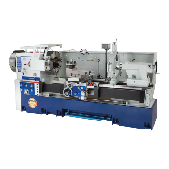
Model SB1065F
Shown with Optional
Accessories
South Bend Tools
© December, 2021 by South Bend Tools
BIG BORE LATHE
MODEL SB1065F 34" X 72"
MODEL SB1066F 34" X 132"
MODEL SB1067F 34" X 212"
MODEL SB1068F 38" X 132"
OWNER'S MANUAL
A Tradition of Excellence
MODEL SB1069F 38" X 212"
MODEL SB1070F 42" X 132"
MODEL SB1071F 42" X 212"
®
For Machines Mfd. Since 07/19 (V1.12.21)
Advertisement
Table of Contents

Related Manuals for South Bend Tools Oil Country Series

Summary of Contents for South Bend Tools Oil Country Series
- Page 1 MODEL SB1067F 34" X 212" MODEL SB1071F 42" X 212" MODEL SB1068F 38" X 132" Model SB1065F Shown with Optional Accessories OWNER'S MANUAL South Bend Tools ® A Tradition of Excellence © December, 2021 by South Bend Tools For Machines Mfd. Since 07/19 (V1.12.21)
- Page 2 We highly value customer feedback on our manuals. If you have a moment, please share your experience using this manual. What did you like about it? Is there anything you would change to make it better? Did it meet your expectations for clarity, professionalism, and ease-of-use? South Bend Tools Technical Documentation Manager P.O. Box 2027 Bellingham, WA 98227 Email: manuals@southbendtools.com...
-
Page 3: Table Of Contents
Table of Contents INTRODUCTION ............2 ACCESSORIES ...........39 About This Machine ..........2 MAINTENANCE ...........40 Identification ............3 Maintenance Schedule ........40 Description of Controls & Components ....4 Cleaning & Protecting ........40 SAFETY ..............10 Maintenance Checklist ........41 Understanding Risks of Machinery ....10 LUBRICATION .............42 Additional Metal Lathe Safety ...... -
Page 4: Introduction
Thick castings, heavy mass, and quality construction throughout provide the necessary brawn for demanding production and manufacturing tasks. South Bend Tools... -
Page 5: Identification
Halogen Work Lamp Four-Position Apron Stop G. Fagor DRO Control Panel Q. Removable Gap H. Four-Way Tool Post (Optional) R. Headstock Control Panel Steady Rest (Optional) Gearbox Feed Controls 2-Speed Tailstock w/MT#6 Morse Taper Headstock Spindle Controls Quill South Bend Tools... -
Page 6: Description Of Controls & Components
Gearbox Speed Dial: Controls leadscrew and feed rod speed for the cutting pitch selected by the lettered gearbox levers. South Bend Tools... - Page 7 Foot Brake Mode: When in this mode, foot brake is pressed partially down to turn OFF Figure 3. Headstock control panel. Figure 3. Headstock control panel. spindle motor. Next user presses foot pedal remaining distance in a sustained manner to apply band brake. South Bend Tools...
- Page 8 Once after brake is used, you must reset or cycle spindle switches by turning them OFF then back ON again before spindle rotation can be re- started. Figure 4. Carriage control panel. Figure 4. Carriage control panel. South Bend Tools...
- Page 9 H. 4-Position Apron Stop: Contacts adjustable apron stop lobes, and disengages apron from feeding operations. Figure 8. Feed clutch control knob. Figure 8. Feed clutch control knob. Figure 7. Apron controls. Figure 7. Apron controls. South Bend Tools...
- Page 10 Compound Rosette: The scale indicates at Tailstock Handwheel: A cast-iron handwheel which angle compound is set to move. moves quill toward or away from spindle. South Bend Tools...
- Page 11 H. Offset Lock: Two cap screws clamp together upper and lower halves of tailstock after offset is adjusted. Tailstock Stop: Prevents tailstock from sliding off of ways. Figure 11. Tailstock rear controls. Figure 11. Tailstock rear controls. South Bend Tools...
-
Page 12: Safety
Reduce your risks from these hazards or crushing injuries. Reduce this risk by by wearing approved eye protection, keeping any included guards/covers/doors respirator, gloves, or hearing protection. installed, fully functional, and positioned for maximum protection. South Bend Tools -10-... - Page 13 Technical Support for assistance. rotate. South Bend Tools -11-...
-
Page 14: Additional Metal Lathe Safety
Clearing Chips. Metal chips can be razor sharp. Measuring Workpiece. To reduce risk of Avoid clearing them by hand or with a rag. entanglement, never measure rotating Use a brush or vacuum instead. workpieces. South Bend Tools -12-... -
Page 15: Additional Chuck Safety
To reduce the risk of this hazard, read or installing the chuck. Always disconnect and understand this document and seek the lathe from power before performing additional training from an experienced these procedures. chuck user before using a chuck. South Bend Tools -13-... -
Page 16: Preparation
Cleaner/Degreaser (refer to Page 17) • • Quality metal protectant oil 10. Prepare lathe for full operation. • Safety glasses for each person • Basic hand tools • Floor mounting hardware (refer to Page 20) South Bend Tools -14-... -
Page 17: Power Supply Requirements
To reduce the risk of these hazards, avoid overloading the machine during operation and make sure it is connected to a power supply circuit that meets the requirements in the following section. South Bend Tools -15-... -
Page 18: Unpacking
Note: Additional documentation pertaining to the electrical system is shipped inside of the lathe electrical cabinet. South Bend Tools -16-... -
Page 19: Cleaning & Protecting
Avoid using these could damage them or make them slip during products to remove rust operations. preventative. Many cleaning solvents are toxic if inhaled. Minimize your risk by only using these products in a well ventilated area. South Bend Tools -17-... -
Page 20: Location
Minimum Working Clearances - Add 32" at the Shown Locations for the Lathe Purchased. Refer to Applicable Data Sheet for Overall Dimensions of Your Lathe Model. Figure Figure 13. Minimum working clearances (All models). 13. Minimum working clearances (All models). South Bend Tools -18-... -
Page 21: Lifting & Moving
Unbolt lathe from shipping pallet. Protect bed and any other lathe surface from potential damage from lifting equipment. Figure 15. Example of chain or strap spreader. Figure 15. Example of chain or strap spreader. South Bend Tools -19-... -
Page 22: Leveling & Mounting
Leveling machinery helps precision components, such as bedways, remain straight and flat during the lifespan of the machine. Components on a machine that is not level may slowly twist due to the dynamic loads placed on the machine during operation. South Bend Tools -20-... -
Page 23: Assembly
This can be accomplished by following the maintenance schedule on Page 40. Incoming Power Incoming Power Strain Relief Strain Relief Figure 18. Electrical cabinet. Figure 18. Electrical cabinet. South Bend Tools -21-... -
Page 24: Test Run
DO NOT start machine until all preceding setup instructions have been performed. Operating an improperly set up machine may result in malfunction or unexpected results that can lead to serious injury, death, or machine/property damage. South Bend Tools -22-... - Page 25 Make sure headstock, gearbox, and apron oil levels are at full mark indicated by sight Figure 21. Headstock control panel. Figure 21. Headstock control panel. glasses. Turn coolant pump switch to OFF position, and point coolant nozzle into chip pan. South Bend Tools -23-...
- Page 26 ON/OFF levers box. (see Figure 24). 11. Unlock carriage lock and use carriage handwheel to move carriage back and forth to ensure it is disengaged from leadscrew and feed rod. South Bend Tools -24-...
- Page 27 Figure 27. Carriage control panel. Figure 27. Carriage control panel. 29. On both control panels, press Jog button to bump spindle. 30. Restart lathe and press foot brake; lathe should quickly stop. South Bend Tools -25-...
-
Page 28: Spindle Break-In
Half Nut Clamping (Page 53). • run. • Leadscrew/Feed Rod End Play (Page 53). Foot Brake/Motor Brake (Page 54). • • V-belts (Page 55). South Bend Tools -26-... -
Page 29: Operation
14. When finished cutting, shuts down lathe and removes workpiece. 15. Returns power feed levers to Neutral or their disengaged positions. South Bend Tools -27-... -
Page 30: Tailstock
Set Screw Scale Scale (1 of 4) (1 of 4) (1 of 2) (1 of 2) Figure 31. Tailstock offset controls. Figure 31. Tailstock offset controls. Figure 29. Tailstock graduated dial. Figure 29. Tailstock graduated dial. South Bend Tools -28-... -
Page 31: Chucks & Faceplates
(see Figure 31). The jack screws tilt or raise tailstock centerline with spindle. The factory has adjusted these, and readjustment is not typically required for the life of the lathe. South Bend Tools -29-... -
Page 32: Spindle Speed
Now move Range lever to L, M, or H. L will give you 20 RPM M will give you 85 RPM H will give you 500 RPM Repeat this procedure for other three speed groups when needed. South Bend Tools -30-... -
Page 33: Manual Feed
One full rotation moves the carriage 1.00" Inch Graduations ..........0.010" Metric Graduations .......... N/A Figure 40. Cross slide handwheel scale. Figure 40. Cross slide handwheel scale. Figure 39. Carriage handwheel scale. Figure 39. Carriage handwheel scale. South Bend Tools -31-... -
Page 34: Quick Traverse
Turn traverse motor directional switch (see Figure 44) to the desired rapid traverse direction. Hold quick traverse lever (see Figure 43) in Figure 42. Compound rest graduated dial. Figure 42. Compound rest graduated dial. its up position for motorized travel. South Bend Tools -32-... -
Page 35: Power Feed
(and sometimes spindle speed) to achieve the best results. The carriage can alternatively be driven by the leadscrew for threading operations (refer to Inch-Thread Dial on Page 36). South Bend Tools -33-... - Page 36 Feed Direction knob consistent feeding without disengagement, and lever on the apron, the actual direction of while still providing overload protection. power feed will respectively change from the printed indicators on the machine! South Bend Tools -34-...
- Page 37 The process is the same for setting the cross feed rate and threading selections. Refer to Feed Chart in Figure 51 for all available feeds. Figure 49. Feed mode lever (IN MM mode). Figure 49. Feed mode lever (IN MM mode). South Bend Tools -35-...
- Page 38 When threading, we recommend using the slowest speed possible and avoiding deep cuts, so you can more easily disengage the Figure 51. Threading and feed rate chart. Figure 51. Threading and feed rate chart. half nut to prevent an apron crash! South Bend Tools -36-...
- Page 39 Figure 57. Thread dial positions for odd threads. Figure 57. Thread dial positions for odd threads. Positions: Positions: 2, 4, 6, 8,10,12 14,16,18,20,22 All 8 24,26,28 Figure 54. Thread dial positions for even threads. Figure 54. Thread dial positions for even threads. South Bend Tools -37-...
-
Page 40: Four-Position Apron
IMPORTANT: Promptly clean any splashed fluid from floor to avoid a slipping hazard. Clutch Clutch Release Release Lever Lever Figure 58. Four-position apron stop mechanism. Figure 58. Four-position apron stop mechanism. South Bend Tools -38-... -
Page 41: Accessories
" Steady Rest w/ Rollers (Clamping: 290~590mm) SB1084 ⁄ " Steady Rest w/ Rollers (Clamping: 340~700mm) SB1085 Taper Turning Attachment SB1086 Four-Position Apron Stop SB1087 Micro Carriage Stop SB1088 MT6 Heavy Duty Live Center SB1089 Quick Change Post South Bend Tools -39-... -
Page 42: Maintenance
Add oil to ball oilers (Page 45). • a thin film of oil is all that is necessary for • Clean/lubricate leadscrew (Page 45). protection. Ensure carriage lock lever is loose (Figure 7 • on Page 7). South Bend Tools -40-... -
Page 43: Maintenance Checklist
M A I N T E N A N C E For Machines Mfd. Since 7/19 Model SB1065F–SB1071F Maintenance Chart South Bend Tools -41-... -
Page 44: Lubrication
Rags ............As Needed Oil Fill Oil Fill Oil Sight Glass Oil Sight Glass Figure 59. Headstock oil level sight glass. Figure 59. Headstock oil level sight glass. Figure Figure 61. Headstock fill cap. 61. Headstock fill cap. South Bend Tools -42-... -
Page 45: Gearbox
Figure 63. Location of apron oil sight glass. Figure 63. Location of apron oil sight glass. Oil Drain Plug Oil Drain Plug Figure 62. Gearbox oil sight glass and plugs. Figure 62. Gearbox oil sight glass and plugs. South Bend Tools -43-... - Page 46 The apron is now flushed of loose particles. Figure 64. Apron drain plug. Figure 64. Apron drain plug. Remove fill plug (see Figure 65), and remove drain plug using a 5mm hex wrench. South Bend Tools -44-...
-
Page 47: Hand-Pump Oiler
Pump oil can once or twice. If you see sludge and contaminants coming out of lubrication Repeat this process while moving carriage area, keep pumping oil can until oil is clear. and cross slide through their full range of movement to distribute oil along ways. South Bend Tools -45-... -
Page 48: End Gears
Make sure end gear cover remains installed whenever possible to keep gears free of dust or debris from outside environment. Figure 69. Compound ball oilers. Figure 69. Compound ball oilers. South Bend Tools -46-... -
Page 49: Tailstock Gearbox
Small Stiff Brush for Grease ........ 1 Hex Wrench 3mm ..........1 Apply a generous coat of grease to gear teeth Mineral Spirits ........As Needed and rotate controls to distribute grease. Rags ............As Needed Re-install access cover. South Bend Tools -47-... -
Page 50: Coolant Service
Figure 74 and remove pump. Use the correct personal protection equipment when Clean-out reservoir and pump intake screen handling coolant. Follow using mineral spirits. federal, state, and fluid manufacturer requirements Using clean rags, dry out reservoir for proper disposal. completely. South Bend Tools -48-... -
Page 51: Machine Storage
Run lathe and bring all gearboxes to operating temperature, then drain and refill them with clean oil. Pump out old coolant, then add a few drops of way oil and blow out lines with compressed air. DISCONNECT LATHE FROM POWER! South Bend Tools -49-... -
Page 52: Service
Figure 75. Compound rest leadscrew adjustment. Figure 75. Compound rest leadscrew adjustment. the handwheel dial. To adjust backlash, rock the handwheel back and forth, while tightening the screws slowly until the backlash is approximately 0.002"–0.003", as indicated on the graduated dial. South Bend Tools -50-... -
Page 53: Gib Adjustments
Front Gib Screw Screw Front Gib Front Gib Figure 78. Cross slide gib adjustment screw. Figure 78. Cross slide gib adjustment screw. Screw Screw Figure 77. Compound rest leadscrew adjustment. Figure 77. Compound rest leadscrew adjustment. South Bend Tools -51-... - Page 54 Figure 80. Rear saddle gib screws. Figure 80. Rear saddle gib screws. adjustment by using offset adjustment cap screws. Use a flat head screwdriver to adjust gib in or out. When you are satisfied with setting, retighten clamping hex bolts. South Bend Tools -52-...
-
Page 55: Half Nut Clamping
If tension is felt at the beginning of lever travel, the adjustment is too tight and must be loosened slightly. South Bend Tools -53-... -
Page 56: Brake Service
At brake band adjustment stud, use a 14mm Spindle Motor Spindle Motor wrench to adjust nuts and pull brake band closer to hub. Electric Motor Brake Electric Motor Brake Figure 84. Motor brake system. Figure 84. Motor brake system. South Bend Tools -54-... -
Page 57: Adjusting V-Belts
Figure 86. Pivoting motor mount plate. Tighten hex nuts against both sides of motor mount plate to prevent it from moving out of adjustment during operation, then re-install access covers. Close and tighten motor access door cap screw. South Bend Tools -55-... -
Page 58: Replacing Shear Pins
Screw (1 of 10) Put on safety goggles. Figure 88. Shear pin access. Figure 88. Shear pin access. Remove two cap screws holding retractable curtain support bracket (see Figure 87) to lathe headstock, and carefully set aside. South Bend Tools -56-... - Page 59 10. Rotate shaft and hub so smaller end of tapered bore or pin is facing you. 11. Use a ⁄ dowel punch and hammer to lightly " " tap out broken shear pin pieces. South Bend Tools -57-...
-
Page 60: Removing/Installing Gap Insert
Tighten dowel-pin jack nut until pin is pulled free from gap insert. Figure 92. Gap insert location. Figure 92. Gap insert location. Tap outside of gap insert with a dead blow hammer to loosen it, then remove it. South Bend Tools -58-... - Page 61 Inspect gap alignment 24 hours later to make sure gap is still aligned. If necessary, loosen gap bed cap screws and repeat Steps 7–8 until insert is properly aligned. South Bend Tools -59-...
-
Page 62: Troubleshooting
2. Refer to the feeds and speeds charts in down under load. cutting operation. Machinery's Handbook or a speeds and feeds calculator on the internet. 3. Cutting tool is dull. 3. Sharpen or replace cutting tool. South Bend Tools -60-... - Page 63 3. Adjust gib screws at affected component (see Page 3. Gibs are out of adjustment. cutting. 4. Dull cutting tool. 4. Replace or resharpen cutting tool. 5. Incorrect spindle speed or feed rate. 5. Use recommended spindle speed. South Bend Tools -61-...
- Page 64 8. Replace gears or shear pin (see Page 56). 8. Gears or shear pin broken. Gear change levers 1. Gears not aligned inside headstock. 1. Rotate spindle by hand with light pressure on lever until gear falls into place. will not shift into position. South Bend Tools -62-...
- Page 65 South Bend Tools...
-
Page 67: Warranty
W A R R A N T Y Warranty This quality product is warranted by South Bend Tools to the original buyer for 2 years from the date of purchase. This warranty does not apply to consumable parts, or defects due to any kind of misuse, abuse, negligence, accidents, repairs, alterations or lack of maintenance. - Page 68 southbendtools.com Printed In U.S.A. #CR21874...
Need help?
Do you have a question about the Oil Country Series and is the answer not in the manual?
Questions and answers