Table of Contents
Advertisement
Quick Links
Model: Q 1073A
Auto Ranging True RMS Pro Digital Multimeter
Instruction Manual
Features
• True RMS AC measurement • 6000 count reverse backlit LCD • Autoranging
• Frequency counter to 10MHz • Capacitance measurement • Fused 10A input
• Temperature mode (°C/°F) • Test socket LED lights • Continuity and diode test
• Internal rechargeable lithium battery • Range hold & relative mode • Data hold
• Wireless USB charging adaptor • Cat III 1000V/Cat IV 600V
Advertisement
Table of Contents

Related Manuals for Altronics Q1073A

Summary of Contents for Altronics Q1073A
- Page 1 Model: Q 1073A Auto Ranging True RMS Pro Digital Multimeter Instruction Manual Features • True RMS AC measurement • 6000 count reverse backlit LCD • Autoranging • Frequency counter to 10MHz • Capacitance measurement • Fused 10A input • Temperature mode (°C/°F) • Test socket LED lights • Continuity and diode test •...
- Page 2 Digital Autoranging Multimeter fully tested and calibrated before leaving the production lines. In addition to the standard digital multimeter features, the meter also offer: Non-contact Voltage Detector for safely senses electrical sources; Live wire detection Input Jack Indicators to remind users to plug-in the correct jacks;...
-
Page 3: Table Of Contents
TABLE OF CONTENT Read Before Use – Safety Information ....... Symbols ..............The Meter ..............Meter Strurcture ..............3 Charger Structure ..............4 Display ....................4 Push Buttons ..................6 Operating the Meter ............ A. Measuring DC Voltage ............7 B. -
Page 4: Read Before Use - Safety Information
READ BEFORE USE – SAFETY INFORMATION WARNING To possible electrical shock, fire, personal injury and ensure safety operation and service of the equipment, please follow these guidelines: • Read the instruction before use and follow all safety instructions. • Use the equipment only as specified in the instruction card; otherwise, the equipment's safety features may not protect you. -
Page 5: Symbols
terminal and earth ground. • Measure a known voltage first to make sure that the Product operates correctly. • Use the correct terminals, function, and range for measurements. • Do not use test leads if they are damaged. Examine the test leads for damaged insulation, exposed metal, or if the wear indicator shows. -
Page 6: The Meter
Symbol Meaning CAT III IEC Overvoltage Category III CAT III equipment is designed to protect against transients in equipment in fixedequipment installations, such as distribution panels, feeders and short branch circuits, and lighting systems in large buildings. CAT IV IEC Overvoltage Category IV CAT IV equipment is designed to protect against transients from the primary supply level, such as an electricity meter or an overhead or underground utility... -
Page 7: Charger Structure
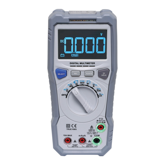
NCV Sensor Rotary Switch Flashlight Input Jacks Holster NCV indicators Display Battery Compartmen CHARGER STRUCTURE 1) USB port 2) Indicator - Error is happened 3) Indicator - Charging DISPLAY Page 4... - Page 8 item Symbol Description Meter is ready for continuity test Meter is ready for non-contact voltage detecting Meter is ready for diode test Minimum reading is displaying Measurement units Volt (unit of voltage) Millivolt Amperes (unit of current) Milliamp A Microamp Ohm (unit of resistance) ...
-
Page 9: Push Buttons
item Symbol Description Display Hold is active Measuring AC Negative sign Measuring DC Dangerous Voltages PUSH BUTTONS Button Mode Function Access S e l e c t s a l t e r n a t e Press once to select the next measurement functions function on a rotary switch setting... -
Page 10: Operating The Meter
OPERATING THE METER Warning To avoid electric shock, fire or personal injury: • Connect the common testlead before the live testlead and remove the live test lead before the common testlead. • Disconnect power and discharge all high-voltage capacitors before you measure resistance, continuity, capacitance, or a diode junction. -
Page 11: Measuring Ac Voltage
1) Insert the testleads as showing in the above figure; 2) Turn the rotary switch to the Volt or millivolt range; 3) Connect the testleads across with the object being measured; 4) The measured value shows on the display; 5) If needed, press to switch to manual ranging, press again to change the range selected. -
Page 12: Measuring Dc Current
1) Insert the testleads as showing in the above figure; 2) Turn the rotary switch to the Volt or millivolt range; 3) Press to switch to AC mode; 4) Connect the testleads across with the object being measured; 5) The measured value shows on the display; 6) If needed, press to switch to manual ranging, press again to change the range selected. -
Page 13: Measuring Ac Current
1) Turn off power to the circuit being test. Discharge all high voltage capacitors; 2) Insert the testleads as showing in the above figure; 3) Turn the rotary switch to the Ampere, Milliamp or MIcroamp range; 4) Open the circuit path to be tested and connect the testleads to the break of the circuit;... -
Page 14: Measuring Resistance
1) Turn off power to the circuit being test. Discharge all high voltage capacitors; 2) Insert the testleads as showing in the above figure; 3) Turn the rotary switch to the Ampere, Milliamp or MIcroamp range; 4) Press to switch to AC mode; 5) Open the circuit path to be tested and connect the testleads to the break of the circuit;... -
Page 15: Continuity Test
1) Insert the testleads as showing in the above figure; 2) Turn the rotary switch to the range; 3) Connect the testleads across with the object being measured; 4) The measured value shows on the display 5) If needed, press to switch to manual ranging, press again to change the range selected. -
Page 16: Diode Test
1) Insert the testleads as showing in the above figure; 2) Turn the rotary switch to the range; 3) Press twice to switch to continuity mode; 4) Connect the testleads across with the object being measured; 5) The measured value shows on the display. G. -
Page 17: Measuring Temperature
H. MEASURING TEMPERATURE Object to be Press Measured Set up to measure temperature 1) Insert the testleads as showing in the above figure; 2) Turn the rotary switch to the °C °F range; 3) Press to switch to select °C mode, press one more to switch to °F mode;... -
Page 18: Measuring Capacitance
Press Turn the Rotary Switch to V, mV, A, mA or uA Set up to measure Frequency J. MEASURING CAPACITANCE Warning • To avoid electric shock, do not test on circuits or devices with 60V DC or 30V rms AC. •... -
Page 19: Detecting Live Wire
K. LIVE WIRE DETECTION Warning • Always hold the Product behind the tactile barrier. • Do not input voltage over 1000V. Press Live Set up to find live wire 1) Insert the red testleads as showing in the above figure; 2) Turn the rotary switch to the NCV Live range;... -
Page 20: Relative Mode
Set up to detect Voltage (non-contact) 1) Turn the rotary switch to the NCV range; 2) EF is displayed; 3) Place the NCV sensor tip close to the source of electrical energy being test; 4) If voltage is detected, the Meter will beep and "-" will appear on the display and the NCV indicator(s) will switch on. -
Page 21: Flashlight And Display Backlight
N. FLASHLIGHT AND DISPLAY BACKLIGHT Flashlight Hold down the button to switch on the flashlight. Hold down the button again will switch off the flashlight. Display Backlight Hold down the button to switch on the display backlight. Hold down the button again to switch off the display backlight. O. -
Page 22: Specifications
SPECIFICATIONS Maximum Display 5999 Measurement Rate 3 times / second Temperature Operating: 0°C ~ 40°C Storage: -10°C ~ 50°C Relative Humidity <90% Battery 14500 x 1 Fuse(s) 1A, 1000V, 6x30mm 10A, 1000V, 10x38mm Size 192 x 89 x 43mm Weight ~380g (include battery) Accuracy is specified for 1 year after calibration, at operating temperatures... - Page 23 Function Range Resolution Accuracy Overload Protection ±([% of Reading] + [Counts]) DC Current 600 A 0.1 A ±(1.2%+5) 1A, 1000V, fuse 6000 A 1 A 60mA 0.01mA 600mA 0.1mA 0.01A ±(2%+5) 10A, 1000V, fuse AC Current 600 ...
-
Page 24: Maintenance
Function Range Resolution Accuracy Overload ±([% of Reading] + [Counts]) Protection Frequency 10Hz 0.01Hz ±(1.5%+5) 1000V 100Hz 0.1Hz 1kHz 0.001kHz 10kHz 0.01kHz 100kHz 0.1kHz 1MHz 0.001MHz 10MHz 0.01MHz Sensitivity: < 1kHz : 200mVp-p 1kHz : 3Vp-p Capacitance 0.001nF ±(5%+5) 1000V 60nF 0.01nF ±(4%+5) -
Page 25: Charging
CHARGING Caution Users are allowed to charge the batteries of only. To protect the user and the equipment, remove all connections before charging. Never connect the meter during charging. Please charge the Meters immediately by using the charger provided and connect as following figure if the battery indicator is on. -
Page 26: Cleaning
CLEANING Caution To avoid damaging the equipment, NEVER submerge them in water. DO NOT use abrasive cleaners, they will damage the case. Wipe the case with a damp cloth and mild detergent. Do not use abrasives or solvents. Dirt or moisture in the jacks can affect the measurement. Page 2...
Need help?
Do you have a question about the Q1073A and is the answer not in the manual?
Questions and answers