Advertisement
Table of Contents
- 1 Ec Declaration of Conformity
- 2 Intended Use
- 3 Specifications
- 4 Installation Safety Guidelines
- 5 Installation - Mechanical Components
- 6 Installation - Electrical/Electronic Components
- 7 Operation - Safety Guidelines
- 8 Operation - Motor Units
- 9 Operation - Remote Control Handset
- 10 Operation - Electronic Control Unit
- 11 Operation - Getting Started
- 12 Operation - Hitching and Unhitching
- 13 Troubleshooting
- Download this manual
Advertisement
Table of Contents

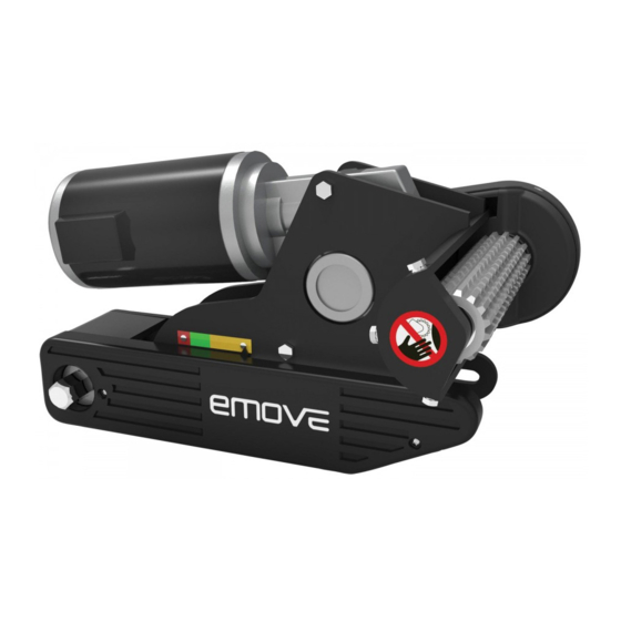
Summary of Contents for LEISUREWIZE EMOVE EM203
- Page 1 EM203 Manual AW 11-2020.qxp_Layout 1 30/11/2020 08:36 Page 2 ® EM203 Caravan Manoeuvring System...
-
Page 2: Ec Declaration Of Conformity
EM203 Manual AW 11-2020.qxp_Layout 1 18/11/2020 09:01 Page 3 PACKAGE CONTENTS (Parts list) Description Cable ties 2x70 Motor unit (A) Battery isolation switch, cover & key Motor unit (B) Roller distance spacers 20x20 Main crossbar Remote control handset with lanyard Cross actuation centre bar Electronic control unit Cross actuation insert bars... -
Page 3: Intended Use
EM203 Manual AW 11-2020.qxp_Layout 1 18/11/2020 09:01 Page 4 INTRODUCTION Congratulations on choosing the emove EM203 caravan manoeuvring system. This has been produced according to very high standards and has undergone careful quality control procedures. Simply by using the remote control handset you can move your caravan effortlessly into any position required within operating guidelines. -
Page 4: Installation - Mechanical Components
EM203 Manual AW 11-2020.qxp_Layout 1 18/11/2020 09:01 Page 5 Check that the tyres are not over worn and do have the same size and design (fitting to new or nearly new tyres is the best option). Make sure that the tyre-pressures are correct to the manufacturer’s recommendation. Make sure the chassis is in good condition without any damage and is free from rust, dirt etc. -
Page 5: Installation - Electrical/Electronic Components
EM203 Manual AW 11-2020.qxp_Layout 1 18/11/2020 09:01 Page 6 With the main assembly is loosely fitted onto the chassis, slide the whole assembly along the chassis until the rollers are 20mm away from the surface of the centre each tyre (Fig. 10). Two 20mm spacers (30) are provided. It is vitally important that each roller is at exactly the same distance away from the tyre. -
Page 6: Operation - Safety Guidelines
EM203 Manual AW 11-2020.qxp_Layout 1 18/11/2020 09:01 Page 7 Route the motor cables along the underside of the caravan floor, inside the supplied convoluted trunking (11) (this will protect the electrical cables against sharp edges and dirt) and through the drilled hole. Secure the cable trunking (11) to the chassis or under body of the caravan by using the P-Clips (20) and screws (19). -
Page 7: Operation - Motor Units
EM203 Manual AW 11-2020.qxp_Layout 1 18/11/2020 09:01 Page 8 Due to the nature of a radio signal, it can get corrupted by external terrain or objects. So there may be small areas around the caravan where the quality of reception reduces, hence the manoeuvring system may stop momentarily. -
Page 8: Operation - Remote Control Handset
EM203 Manual AW 11-2020.qxp_Layout 1 18/11/2020 09:01 Page 9 If the pointer is in the red area – Rollers are connected to the tyre but in an extreme position. It could be that the tyre of the caravan has insufficient air pressure or the drive unit has been knocked out of position PERATION - REMOTE CONTROL and a visit to a workshop is required to reposition the assembly. -
Page 9: Operation - Electronic Control Unit
EM203 Manual AW 11-2020.qxp_Layout 1 18/11/2020 09:01 Page 10 Install a new replacement battery (Fig. 7.1). Make sure to use a leak proof PP3 (9Volt) battery (No claims under guarantee can be considered for damage caused by leaking batteries). Close the rear cover again. Dead and used batteries may leak and damage the remote control handset! Remove the batteries if the handset is not going to be used for an extended period. -
Page 10: Operation - Hitching And Unhitching
EM203 Manual AW 11-2020.qxp_Layout 1 18/11/2020 09:01 Page 11 Now you can choose the movements according the symbols shown on the remote control. Straight forward (Fig. 5B), straight reverse (Fig. 5C ), left forward (Fig. 5D), left reverse (Fig. 5F), right forward (Fig. 5E), right reverse (Fig. -
Page 11: Troubleshooting
EM203 Manual AW 11-2020.qxp_Layout 1 18/11/2020 09:01 Page 12 Regularly clean the drive units with a water hose to dissolve mud etc. Please check regularly the distance between the rollers and the tyres. In the neutral (fully disengaged) position this must be about 20mm. Once a year have your caravan manoeuvring system maintained and visually inspected. - Page 12 EM203 Manual AW 11-2020.qxp_Layout 1 18/11/2020 09:02 Page 13 Check if there is any distortion signal (other transmitter , high power cables, Wifi etc.) that disturbs a good communication between remote control handset and control unit. If there is no good communication between the control unit and remote control handset, the manoeuvring system will not function and the green LED on remote control handset will blink.
- Page 13 EM203 Manual AW 11-2020.qxp_Layout 1 18/11/2020 09:02 Page 14...
- Page 14 EM203 Manual AW 11-2020.qxp_Layout 1 18/11/2020 09:02 Page 15...
- Page 15 EM203 Manual AW 11-2020.qxp_Layout 1 18/11/2020 09:02 Page 16...
- Page 16 EM203 Manual AW 11-2020.qxp_Layout 1 18/11/2020 09:02 Page 1 Streetwize: For product support: For trade enquiries: For spare parts: Ashburton Road West, Trafford Park, E: support@streetwizeaccessories.com E: sales@streetwizeaccessories.com E: spareparts@streetwizeaccessories.com Manchester M17 1RY T: +44 (0)161 447 8597 T: +44 (0)161 447 8580 www.streetwizeaccessories.com EU Registered address: The Ace Supply Co (Europe) Ltd, 25 Herbert Place, Dublin 2, D02 A098 Republic of Ireland.


Need help?
Do you have a question about the EMOVE EM203 and is the answer not in the manual?
Questions and answers
Picture of all components