Advertisement
Quick Links
Advertisement

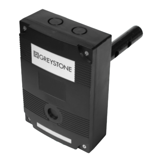
Summary of Contents for Greystone AIR-300
- Page 1 AIR-300 Air Quality Controller Installation and Operating Instructions Febuary 15, 2005...
- Page 2 Introduction The Air Quality Monitor uses a tin dioxide semiconductor sensor based on the Taguchi principle to detect oxidizable gases and is specially designed to have high sensitivity to gaseous organic materials which are components of indoor air pollutants. The sensor is essentially a heated element inside a porous semiconductive tube.
- Page 3 This device is a 3-wire sourcing type transmitter. Connect the positive dc voltage or the hot side of the ac voltage to the terminal marked PWR. The power supply common is connected to the terminal marked COM. The device is reverse voltage protected and will not operate if connected backwards.
- Page 4 Air Condition Examples Internal Sensor Signal 0-5 Volt Linear Output Signal Clean fresh air 1. 50 volts 1.0 volts = 10 % pollution Early morning in an un-occupied office 1.75 volts 1.0 volts = 15 % pollution Smoke from one cigarette in a 300 ft room 2.00 volts 1.6 volts = 40 % pollution...
- Page 5 saturated (cannot be improved with fresh air intake) and the base level is raised to equal the current level and the output is set back to This cycle is repeated constantly, with the base level being updated as soon as a lower air reading is obtained, to ensure the air quality is kept at the optimum value and that energy efficiency is not sacrificed.
- Page 6 Linear Output The optional linear output terminal provides either a 0-5 Vdc, 0-10 Vdc or 4-20 mA signal to the automation system to represent the degree of pollution. This signal is temperature compensated to provide an accurate and reliable method of tracking the air contaminants. The output signal type is selected via clearly marked jumpers on the PCB.
- Page 7 Configuration Menu Values Menu Mode Default Value Linear Output Range LED Status AUTO LED indicates status Manual/Auto Auto OK and LOW flash ASO (HIGH LED flashes) Relay Mode Linear (MID LED flashes) ASO – HIGH LOW, MID or HIGH LED is lit Linear –...
- Page 8 Wiring Diagram Power Supply /Output Common 20-30Vac/dc Analog Stepped Output Relay (to damper actuator) Connection (Optional) Linear Output (current or voltage) (to B.A.S.) (Optional)