
Summary of Contents for Tescom Ts2
- Page 1 Ts2 Clock Multi-Sync Gateway USER GUIDE SJC-DEV7250-HR © 2021 TesCom All Rights Reserved.
- Page 2 Copyright Copyright Copyright © 2020 TesCom All rights reserved. No part of this document may be reproduced or translated into any language by any means without the written permission of TesCom. Throughout this document TesCom will be referred to as TesCom.
- Page 3 Disclaimer Disclaimer TesCom makes no warranties for the contents of this document or the accuracy or completeness thereof and disclaims any implied warranties of merchantability or fitness for any particular purpose. Further, TesCom reserves the right to revise this document and to make changes without notifications to any person of such changes.
-
Page 4: Table Of Contents
Applying Power ........................12 Getting Started ..........................13 Logging in with the console ....................13 Set up IP address ........................13 Remote Network Access to Ts2 ....................13 Command Reference ........................15 Ts2 Basic Commands ......................15 Show commands ........................16 Inventory commands ...................... - Page 5 Qg 2 Multi-Sync Gateway User Guide Introduction Ts2 Engine Modes ........................26 GNSS Interface ........................27 Ts2 Clock Sync States ......................27 Unicast Operations ......................... 28 Gateway and Boundary clock ....................29 PTP Servo Configuration Parameters ..................30 Synchronous Ethernet (SyncE) ....................31 Physical Interfaces .........................
- Page 6 Introduction List of Figures Figure 1 The Ts2 ............................7 Figure 2 The Ts2 Front Panel ........................7 Figure 3 The Ts2 Rear Panel ........................8 Figure 4 Ts2 Components Block Diagram ....................9 Figure 5 Help Command ........................15 Figure 6 History Command ........................
- Page 7 Qg 2 Multi-Sync Gateway User Guide Introduction List of Tables Table 1 Ts2 Rear Panel Interfaces ......................8 SJC-DEV7250-HR Rev. 1.14...
-
Page 8: Introduction
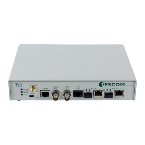
Grand Master and Boundary Clock functionality. IEEE 1588-2008 PTP is also known as PTP Version 2. Figure 1 The Ts2 Ts2 gets its time from the built-in GNSS receiver or 1PPS/ToD input or IEEE 1588-2008 PTP as input references. PTP algorithms are leveraged to deliver stringent timing for frequency and phase profiles. -
Page 9: Typical Applications
1.5 PTP Slave Capacity The Ts2 has variants that can support different unicast slave capacity (32, 128, 256, ..) slaves at up to 128 sync / delay packets per second when the MCE is operated as a master clock depending on the product SKU. -
Page 10: Figure 4 Ts2 Components Block Diagram
Qg 2 Multi-Sync Gateway User Guide Introduction Figure 4 Ts2 Components Block Diagram Managed Clock Engine (MCE) is a full packet network-based synchronization engine supporting IEEE 1588-2008 Precise Time Protocol. The MCE is where IEEE 1588-2008 PTP packet communication processing runs, and port / BNC provisioning is applied. GNSS signals and User Interface Processor (UIP) commands are sent to the MCE. -
Page 11: Installation
Contact your TesCom distributor if the model or serial number do not match. 2.4 Rack Mounting the Ts2 The Ts2 is half of a 19-inch rack, and occupies 1.75 in (4.5 cm, 1RU) of vertical rack space. An optional mounting bracket can be provided by the local distributor. -
Page 12: Power And Ground Connections
PWR B. Ts2 comes equipped with 2 Phoenix connectors to supply PWR A and PWR B and the user needs to connect the two terminals of it to their DC +/- supplies. The Ts2 can also be powered by two VAC power sources, with 28 –... -
Page 13: Connecting Gnss Antenna
2.7 Connecting GNSS Antenna Connect a suitable GNSS antenna, making sure the antenna has a clear view of the sky. When the GNSS receiver has good reception, the GNSS LED will be green. Ts2 provides 5.0 VDC bias to power remote active antennas. -
Page 14: Getting Started
SSH offers a secure shell for users to do remote login to Ts2 using terminal emulation software. After login, the user can use Ts2 CLI to send commands. Note that only SSH and not Telnet access is allowed for remote shell login. - Page 15 PTPBASE-MIB specification from Timing Over IP Connections and Transfer of Clock (TICTOC) Working Group. 3.3.4 XML API Applications using XML interface can access Ts2 system via its XML API’s. Support for this will be added in future release. SJC-DEV7250-HR Rev. 1.14...
-
Page 16: Command Reference
4 Command Reference 4.1 Ts2 Basic Commands The login credentials for accessing Ts2 CLI shell is admin/admin. This is a list of the available commands related to the control and monitoring of the Ts2. The CLI commands are case insensitive. -
Page 17: Show Commands
The “show” command can be used to show alarms or clock status. 4.2.1 Show Alarms Command This command will display any active Ts2 alarms. If no alarms are present, the Alarm Name and State columns will be blank. Figure 7 Show Alarms Command 4.2.2 Show Status Command... -
Page 18: Network Commands
Command Reference Figure 9 System Info Command 4.3.2 System Upgrade Status Command The Ts2 System Firmware Upgrade Status will be displayed if the upgrade was initiated previously from either CLI or through Web User Interface. Figure 10 System Upgrade Status Command 4.3.3 System Upgrade Start Command... -
Page 19: Figure 12 Network Configure Command
Gateway: 0.0.0.0 4.4.1 Network Configure Command This command lets the user configure Ts2 Management port network parameters. Figure 12 Network Configure Command 4.4.2 Network Status Command Get network status for the Management Port, PTP Timing Port-1, and PTP Timing Port-2. -
Page 20: Https Restore Command
(PEM format) file via Ts2 GUI. Executing this command gives the user to option to reset to factory default – removing the user uploaded SSL certificate file and restoring TesCom’s self-signed certificate. This is needed if wrong user file got uploaded and user is unable to access Ts2 from their browser. Figure 15 HTTPS Restore command 4.6 Date command... -
Page 21: Reboot Command
4.7 Reboot command The Reboot command is to provide for user initiated manual reboot of Ts2 system. Note that a firmware upgrade will automatically initiate reboot of the system. -
Page 22: Troubleshooting And Safety Considerations
This section provides some Ts2 Troubleshooting practices and the indicators for when a problem may be present in the Ts2 operation. Some of the indicators of Ts2 problems are Front Panel LED states, Interface and PTP Webpage statuses and the Error! Reference source not found. Webpage. - Page 23 SMA port. Verity that the GNSS Antenna signal is present. Ts2 Alarm condition is affecting 1 Check the Error! Reference PPS or ToD Input. source not found. Webpage for information about any Ts2 alarms that might affect 1 PPS or ToD Input.
- Page 24 Qg 2 Multi-Sync Gateway User Guide Troubleshooting and Safety Considerations The user has selected external On the Ts2 Front Panel, connect 1PPS / ToD inputs but has not the 1PPS / ToD RJ45 input connected the input sources. source. On the Error! Reference source not found.
- Page 25 Error! Reference source not found. Webpage. Verify that the network routers/switches/hubs between the Ts2 Port 1 and Port 2 and the timing network are properly connected. Port 1 and Port 2 are in the same Make sure that the IP addresses...
-
Page 26: Safety Considerations
When installing or working on the Ts2 equipment, ESD wrist straps should be worn. Use the specified power supply and ground for the Ts2 equipment as stated in the Power and Ground Connections section. Refer to the Applying Power section when applying power to the Ts2 equipment. -
Page 27: Managed Clock Engine Overview
PRC_DEGRADATION_B (187) or APP_DEGRADATION_B (193), so clock can potentially become a PTP slave if a better clock appears on the network. This mode means that the Ts2 clock has the GNSS-signal as its primary source of synchronization and the PTP as a backup source, i.e. when no GNSS-signal present. -
Page 28: Gnss Interface
UNKNOWN/ERROR 6.3.1 FREE RUNNING State The Ts2 clock comes into this state upon initialization. The Ts2 clock time is not set, the clock class is DEFAULT (248), clock accuracy is UNKNOWN (0xFE). The timescale is PTP, the UTC offset is initially set to 37 secs, leap flags are FALSE. In Free Running state, the clock frequency comes from the on-board oscillator. -
Page 29: Unicast Operations
(if valid) and leap flags are also set to master’s values and the time source is set to PTP. 6.3.4 HOLDOVER State The Ts2 clock enters this state when the synchronization source is lost. If the clock was synchronized with PTP master its clock class remains unchanged. Otherwise the clock class is modified according the engine’s operational mode and the clock accuracy is changed based on the time spent in the holdover... -
Page 30: Gateway And Boundary Clock
6.5 Gateway and Boundary clock The Ts2 Multi-Sync Gateway has the capability of using both of its Ethernet ports (Port 1 and Port 2) as PTP ports. This opens the possibility of using the Ts2 as a two-port gateway or boundary clock. For more information about Gateway and Boundary Clocks, see [1]. -
Page 31: Ptp Servo Configuration Parameters
Qg 2 Multi-Sync Gateway User Guide Managed Clock Engine Overview Another capability of the Ts2 is for both ports to be configured as master ports. In that configuration, each port would have its own IP address and be associated with different subnets. However, both ports would have the same PTP Clock Identity. -
Page 32: Synchronous Ethernet (Synce)
(e.g. 300 sec) would be a better setting. A longer time constant requires a more stable oscillator to be effective. For example, a time constant above 500 sec requires the Ts2 super OCXO. The default value is 100 sec. -
Page 33: Figure 17 Synce Off
Figure 18 SyncE in Master Mode In this mode of operation, Ts2 is in GNSS-only operating mode where it gets 1pps and ToD signals from a GNSS receiver (internal or external to Ts2), which was originally extracted from GNSS L1 signal . In this mode, the frequency, phase and time references are extracted from GNSS signal, and SyncE is output on SJC-DEV7250-HR Rev. -
Page 34: Figure 19 Synce In Bc Mode For G8275.1, Ref Input On Port-1
PTP-aware and participates in the PTP protocol. When Ts2 is put in Boundary Clock mode in this network, the input SyncE from upstream is used as frequency reference and used directly for SyncE distribution on downstream port. -
Page 35: Figure 21 Synce In Bc Mode For G8275.2, Ref Input On Port-1
Figure 22 SyncE in BC mode for G8275.2, ref input on Port-2 6.7.6 SyncE – additional notes Some additional notes regarding SyncE feature in Ts2: 1. Synchronous Ethernet is supported only for 1GE interface speed. If user had configured previously on Interfaces::PTP webpage for a different Auto-Negotiation and speed parameters, they will be reset to 1000Mbps Full-duplex. - Page 36 Qg 2 Multi-Sync Gateway User Guide Managed Clock Engine Overview SJC-DEV7250-HR Rev. 1.14...
-
Page 37: Physical Interfaces
When Hard Reset Button is pushed and held for a longer duration (approx. 10 seconds), it will do a factory reset of the unit followed by a reboot. The current configuration of Ts2 will NOT be preserved and the user should save and restore their configuration as needed. -
Page 38: Ptp Interface, Port 1 And Port 2
FiberStore (FS): H3C SFP-10GSR-85 (SFP+ dual-rate configured for 1GE) NOTE: SFP Copper modules are also available and will work with Ts2. The user should be aware that in that case, the PHY is inside the SFP Copper and in most cases will not fully support Synchronous Ethernet feature. -
Page 39: Led Description
Qg 2 Multi-Sync Gateway User Guide Physical Interfaces 7.9 LED Description The Ts2 has 3 LED’s on the front panel which communicates the status of the Power, GNSS Signal and Sync Status. 7.9.1 Power Power LED state Description Any of the internal voltages are in alarm state Amber/Orange Initial boot and OS load completed successfully. -
Page 40: End User License Agreement (2020 - 2021)
Software. By installing, copying or otherwise using the SOFTWARE PRODUCT, you agree to be bound by the terms of this EULA. If you do not agree to the terms of this EULA, TesCom is unwilling to license the SOFTWARE PRODUCT to you. - Page 41 6. Limitation of Liability. TesCom's entire liability and your exclusive remedy under this EULA shall not exceed the price paid for the Software, if any. In no event shall TesCom or its suppliers be liable to you for any consequential, special, incidental or indirect damages of any kind arising out of the use or inability to use the software, even if TesCom or its supplier has been advised of the possibility of such damages, or any claim by a third party.
-
Page 42: Part Numbers
Qg 2 Multi-Sync Gateway User Guide Part Numbers 9 Part Numbers Ts2 P/N (GP ID) Description Photo Ts2 w/4-hour holdover (Ts2) Ts2e Ts2 w/8-hour holdover (Ts2e) Ts2RKM19 Kit, Rackmount, 19" (Ts2RKM19) 007-02319-000 Kit, Standard Antenna e/w (007-02319- L1 band, 5VDC, 30dB antenna, 50ft RG58 cable,... -
Page 43: Glossary
Qg 2 Multi-Sync Gateway User Guide Glossary 10 Glossary Acronyms and Abbreviations 1PPS Pulse Per Second 1 Rack Unit, 1.75 inches or 44.45 millimeters Application Program Interface ASCII American Standard Code for Information Interchange BaseT Megabits / second Transferred over CAT5 cable Boundary Clock BMCA Best Master Clock Algorithm... - Page 44 Qg 2 Multi-Sync Gateway User Guide Glossary Phase Locked Loop Power over Ethernet Precise Time Protocol Power Radio Frequency Rack Unit Recommended Minimum data for GPS, Sentence C from NMEA Small Form-Factor Pluggable transceiver SFTP SSH File Transfer Protocol or Secure File Transfer Protocol SubMiniature version A connector SNMP Simple Network Management Protocol...
-
Page 45: References
Qg 2 Multi-Sync Gateway User Guide References 11 References [1] IEEE1588-2008 IEEE Standard for a Precision Clock Synchronization Protocol for Networked Measurement and Control Systems [2] ITU-T G.703 V11, Physical/electrical characteristics of hierarchical digital interfaces [3] M88 Module Design Manual [4] ITU-T G.8261 Timing and synchronization aspects in packet networks [5] ITU-T G.8265.1 Precision time protocol telecom profile for frequency synchronization [6] ITU-T G.703 Transmission Systems and Media, Digital Systems and Networks... -
Page 46: Contact
Qg 2 Multi-Sync Gateway User Guide Contact 12 Contact TesCom Headquarters 20200 Algreg St. Pflugerville TX 78660 U. S. A. Sales Support Phone: +1 (800) 888-1978 Email: sales@tescomusa.com Technical Support Phone: +1 (800) 888-1978 Email: service@tescomusa.com SJC-DEV7250-HR Rev. 1.14...
Need help?
Do you have a question about the Ts2 and is the answer not in the manual?
Questions and answers