
Related Manuals for Viking Range VMTK272


Summary of Contents for Viking Range VMTK272
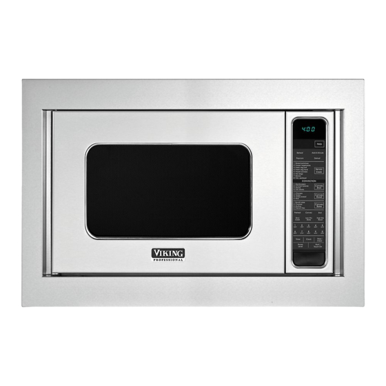
- Page 1 Installation Guide Microwave Built-In Trim Kit VMTK272, VMTK302, VMTK362, VMTK277, VMTK307 VMTK367...
-
Page 2: Important-Please Read And Follow
FOR CUSTOM SERIES MICROWAVE OVEN and the floor line with the floor of the cutout. Tape it into place. 2. For VMTK272, predrill 4 holes marked A with a 1/16" drill bit. For VMTK302, predrill 4 holes marked B with a 1/16" drill bit. -
Page 3: Basic Specifications
Requirements 117vaC/60 Hz (CSa) maximum amp 1.55 kw 13 amps (UL) Usage 1.5 kw 13 (CSa) approximate 60 lbs. (27.2 kg) 19 lbs. (8.6 kg) 20 lbs. (9.1 kg) 23 lbs. 10.5 kg Shipping wt. Description CONVENTIONAL VMOS201/CVMOS201 VMTK272 VMTK302 VMTK362 Overall width 24" (60.9 cm) 26-1/2" (67.3 cm) 29-1/2" (74.9 cm) 35-1/4" (89.5 cm) Overall Height 13-3/8" (33.9 cm) 18-1/4" (46.3 cm) 18-1/4" (46.3 cm) 18-1/4"... -
Page 4: Cabinet Or Wall Cutout
Cabinet or Wall Cutout Exhaust Duct Assembly Provide an opening in the wall or cabinet as indicated in figure . The depth should be a minimum of 20-1/8" DUCT (C) DUCT (B) (51.1 cm). If the Depth (C) dimension is greater than 21" (53.3 cm), the outlet location may be in any area on the rear wall. The floor of the opening should be constructed of plywood strong enough to support the weight of the oven (about 100 lbs.) and should be level for proper SCREw (a) operation of the oven. Note: while the proper functioning of the oven does not EXhAuST DuCT ASSEMBLY: Insert the edge of DUCT (B) into the hold lip of DUCT (C). Secure together by using a SCREw (a) provided require that the opening be enclosed (with sides, ceiling in the kit. See figure 2. and rear partition), this may be required by local code, and it is suggested that the local code be checked for any such requirement. DUCT (a)-1 SCREw (a) DUCT (BC) -
Page 5: Surface Installation
BOTTOM DuCT ASSEMBLY: Place the Bottom Duct in the center of top of the unit as shown and secure the duct assembly to the oven the opening so that gap "a" is equal to gap "B". 1 when the Bottom using the two screws just removed from the oven. See figure 5B. Duct assembly for vmTk277SS, 307SS or 376SS is positioned properly, the front edge of the duct will be flush with the front of the cabinet. *figures 2 - 5 for models vmTk277, 307 and 367 ONLY. 2 The vmTk272SS, 302SS, 372SS Exhaust Duct will be positioned properly when the edge of the duct is recessed 5mm from the front MOuNTINg TEMPLATE: Identify the appropriate side of template of the cabinet. See figure 6. Secure the Bottom Duct assembly with to use with your unit. align the mounting template center line with the two (¾") SCREwS (C). the center of the cutout and the floor line with the floor of the cutout. Tape it into place. • for vmTk272 only, predrill • for vmTk277 only, predrill 4 holes marked “a” with a 4 holes marked “a” with a 1/16" drill bit. 1/16" drill bit. • for vmTk302 only, predrill • for vmTk307 only, predrill 4 holes marked “B” with a 4 holes marked “B” with a 1/16" drill bit. 1/16" drill bit. • for vmTk362 only, predrill • for vmTk367 only, predrill 4 holes marked “C” with a 4 holes marked “C” with a... -
Page 6: Flush Mount Installation
Surface Installation Flush Mount Installation PaRTS INCLUDED IN fLUSH mOUNT aCCESSORy kIT (PURCHaSED SEPaRaTELy): • (2) Stainless Steel Scoops • (10) Stainless machine Screws • (1) flush mount Template • (2) Side Trim fOOT * See fLUSH mOUNT TEmPLaTE for additional installation instructions. BOT TOm DUCT " aSSEmBLy DUCT RECESS CABINET INSTALLATION: avoid pinching the cord between the oven and the wall. adjust the position of the oven so that the feet of the oven are fitted into the holes of the Bottom Duct assembly. See figure 8. SCREw (B) SCREw (B) SCREw (B) SCREw (B) FRAME INSTALLATION: Position the BaCk fRamE to align with the FLuSh MOuNT INSTALLATION: Place the 2 Scoops on the back of predrilled holes that were drilled with the mounting template. Check the frame as shown and align the screw holes on the scoop with the that it is level and then secure with four SCREwS (B). See figure 9. - Page 7 Flush Mount Installation CONVECTION CONVENTIONAL 27" 30" 36" 27" 30" 36" 21-5/16" 21-5/16" 21-5/16" 19-7/8" 19-7/8" 19-7/8" (a) Height (542 cm) (542 cm) (542 cm) (504 cm) (504 cm) (504 cm) 26-15/16" 29-15/16" 35-5/8" 26-15/16" 29-15/16" 35-5/8" (B) width (68.3 cm) (76 cm) (90.4 cm) (68.3 cm) (76 cm) (90.4 cm) (C) Depth 22-1/16" (56.1 cm) 22-1/16" (56.1 cm) min.
-
Page 8: Guide D'installation
Guide d’installation Kit de garniture à encastrer pour four à micro-ondes VMTK272, VMTK302, VMTK362, VMTK277, VMTK307 VMTK367... - Page 9 • L ’installateur devra laisser ces directives au client qui devra les conserver pour l’usage d’un inspecteur local et pour référence ultérieure. • Ce kit à encastrer est destiné à être utilisé UNIQUEmENT avEC LES fOURS À mICRO-ONDES TRaDITIONNELS ET À CONvECTION SPÉCIfIaNT kIT À ENCaSTRER vmTk272, vmTk302, vmTk362, vmTk277, vmTk307 ou vmTk367 sur l'étiquette des spécifications nominales présente sur la plaque frontale inférieure de la cavité du four. • vOTRE fOUR PEUT êTRE INTÉGRÉ DaNS UNE aRmOIRE OU LE mUR LUI-mêmE OU PaR-DESSUS TOUT fOUR ÉLECTRIQUE OU aU mUR OU LE TIROIR DE RÉCHaUffEmENT.
-
Page 10: Spécifications De Base
électrique 117vaC/60 Hz (CSa) 1,55 kw 13 amps (UL) ampèrage max. 1,5 kw 13 (CSa) Poids approx. à 60 lbs. (27,2 kg) 19 lbs. (8,6 kg) 20 lbs. (9,1 kg) 23 lbs. 10,5 kg l’expédition. Descriptión TRADITIONNEL VMOS201 / CVMOS201 VMTK272 VMTK302 VMTK362 35-1/4 po (89,5 cm) Largeur hors tout 24 po (60,9 cm) 26-1/2 po (67,3 cm) 29-1/2 po (74,9 cm) Hauteur hors tout 13-3/8 po (33,9 cm) 18-1/4 po (46,3 cm) 18-1/4 po (46,3 cm) 18-1/4 po... - Page 11 Découpe de l’armoire ou du mur Ensemble du conduit d’évacuation faire une ouverture dans le mur ou l’armoire comme CONDUIT indiqué à schéma . La profondeur doit être au minimum CONDUIT (C) de 20-1/8 po (51,1 cm). Si la profondeur (C) dépasse 21 po (53,3 cm), l'emplacement de la prise peut être situé n'importe où sur le mur arrière. Le plancher de l’ouverture doit être en contreplaqué assez fort pour supporter le vIS (a) poids du four et sa propre charge (environ 45,5 kg [100 lb]). Il doit être à un niveau convenable pour l’utilisation du four. ENSEMBLE Du CONDuIT D’ÉVACuATION : Insérer le bord du CONDUIT (B) dans le joint à lèvre du CONDUIT (C). Les fixer ensemble Remarque : Bien que le bon fonctionnement du four ne à l’aide d’une vIS (a) fournis dans le kit. voir schéma 2.
- Page 12 DE MONTAgE : Déterminer le côté du gabarit qu'il convient de l’ouverture. voir schéma 6. fixer l’ENSEmBLE DU CONDUIT d'utiliser avec votre appareil. aligner la ligne centrale du gabarit de INfÉRIEUR avec deux (¾ po) vIS (C) pour les modèles vmTk302SS, montage avec le centre de la découpe et la ligne de plancher avec vmTk362SS, vmTk307SS et vmTk367SS et utiliser les deux (1-3/16 le plancher de la découpe. Coller en place avec du ruban adhésif. po) (a) pour les modèles vmTk272 et vmTk277. IMPORTANT: fixer les vis à l’aide des trous dans la bride inférieure. • Pour vmTk272 uniquement, • Pour vmTk277 uniquement, percer les 4 trous marqués « percer les 4 trous marqués « a » avec un foret de 1/16 po a » avec un foret de 1/16 po (1,6 mm). (1,6 mm). • Pour vmTk302 uniquement, • Pour vmTk307 uniquement, percer les 4 trous marqués « percer les 4 trous marqués « B » avec un foret de 1/16 po B » avec un foret de 1/16 po...
- Page 13 Installation en surface vIS (B) vIS (B) vIS (B) vIS (B) POSE DANS L’ARMOIRE : Placer le four près de l’ouverture du mur ou de l’armoire. Brancher le cordon d’alimentation dans la prise électrique. Guider avec précaution le four assemblé dans l’ouverture INSTALLATION Du ChÂSSIS : Placer le CHÂSSIS aRRIÈRE pour qu’il préparée. faire glisser le four sur l’ENSEmBLE DU CONDUIT soit aligné avec les trous percés à l’aide du gabarit. vérifier qu’il est de INfÉRIEUR. voir schéma 7. niveau puis le fixer avec quatre vIS (B). voir schéma 9. fixer la partie inférieure de l’ENSEmBLE DU CHÂSSIS avec deux vIS (B) restantes.
- Page 14 Installation du montage encastré Installation PIÈCES INCLUSES DaNS LE kIT D'aCCESSOIRES DE INSTALLATION DE LA DÉCORATION : Placer la décoration avaNT sur le CaDRE et aligner les pivots à rotule avec les récepteurs. fixer mONTaGE ENCaSTRÉ (aCHETÉ SÉPaRÉmENT) : la DÉCORaTION sur le CaDRE en poussant fermement le cadre avant sur le cadre arrière en engageant les quatre (4) fixations à pression. • (2) Boules en acier inoxydable voir schéma !. • (10) vis à métaux inoxydables • (1) Gabarit de montage encastré • (2) Garnitures latérales * voir GaBaRIT DE mONTaGE ENCaSTRÉ pour obtenir des DÉCOUPE POUR instructions d'installation complémentaires. LE mICRO- ONDES "...
-
Page 15: Instrucciones De Instalación
Instrucciones de Instalación Juego de Molduras para Empotrado para Horno Microondas VMTK272, VMTK302, VMTK362, VMTK277, VMTK307 VMTK367... - Page 16 FOR CUSTOM SERIES MICROWAVE OVEN and the floor line with the floor of the cutout. Tape it into place. 2. For VMTK272, predrill 4 holes marked A with a 1/16" drill bit. For VMTK302, predrill 4 holes marked B with a 1/16" drill bit.
-
Page 17: Especificaciones Básicas
117vaC/60 Hz (CSa) Cap. máx. en 1,55 kw 13 amps (UL) amperios 1,5 kw 13 (CSa) Peso aproximado 60 lbs. (27,2 kg) 19 lbs. (8,6 kg) 20 lbs. (9,1 kg) 23 lbs. 10,5 kg de embarque Descripción CONVENCIONAL VMOS201/CVMOS201 VMTK272 VMTK302 VMTK362 ancho total 24" (60,9 cm) 26-1/2" (67,3 cm) 29-1/2" (74,9 cm) 35-1/4" (89,5 cm) altura total desde la parte 13-3/8" (33,9 cm) 18-1/4" (46,3 cm) 18-1/4" (46,3 cm) 18-1/4"... - Page 18 Abertura del gabinete o pared Ensamblaje del ducto de escape Haga una abertura en la pared o en el gabinete como se DUCTO (C) indica en la figura 1. La profundidad debe tener un mínimo DUCTO (B) de 20-1/8" (51.1 cm). Si la dimensión de la profundidad (C) es mayor a 21" (53.3 cm), la ubicación de la toma de corriente puede estar en cualquier área de la pared posterior. La superficie de la abertura debe ser construida de madera laminada lo suficientemente resistente para TORNILLO (a) soportar el peso del horno (aproximadamente 100 libras) y debe ser nivelada para obtener un funcionamiento ENSAMBLAJE DEL DuCTO DE ESCAPE: Inserte el extremo del adecuado del horno.
- Page 19 307SS o 376SS esté colocado correctamente en la *figuras 2 - 5SÓLO para modelos vmTk277, 307 y 367. abertura, el borde frontal del conjunto del ducto estará al ras con la parte frontal del gabinete. 2 El vmTk272SS, 302SS o 372SS del PLANTILLA DE MONTAJE: Identifique el lado apropiado de la DUCTO DE ESCaPE será coloca correctamente cuando el borde de plantilla para utilizar con la unidad. alinee la línea central de la plantilla la ducto está empotrado 5mm desde la frontal del gabinete. vea la de montaje con el centro del recorte y la línea del piso con el piso del figura 6. asegure el conjunto del ducto inferior con dos TORNILLOS recorte. asegúrelo con cinta adhesiva. (de ¾") (C). • Sólo para vmTk272, taladre • Sólo para vmTk277, taladre 4 agujeros marcados como 4 agujeros marcados como "a" con una broca de 1/16". "a" con una broca de 1/16". • Sólo para vmTk302, taladre • Sólo para vmTk307, taladre 4 agujeros marcados como 4 agujeros marcados como "B" con una broca de 1/16". "B" con una broca de 1/16".
- Page 20 Instalación en superficie Instalación del montaje al ras PaRTES INCLUIDaS EN EL JUEGO DE aCCESORIO DE mONTaJE (SE COmPRa POR SEPaRaDO) : • (2) De acero inoxidable bolas • (10) Tornillos inoxidables de máquina • (1) Plantilla para montaje al ras • (2) molduras laterales BaSE * vea PLaNTILLa DE mONTaJE aL RaS para instrucciones adicionales de instalación. CON JUN TO DEL DUCTO " INfERIOR CavIDaD DEL DUCTO INSTALACIÓN EN gABINETE: Evite que el cable quede entre el horno y la pared. ajuste la posición del horno de modo que las patas del horno encajen en los agujeros del CONJUNTO DEL DUCTO INfERIOR. vea la figura 8.
-
Page 21: Instalación
Instalación del montaje al ras CONVECCIÓN CONVENCIONAL 27" 30" 36" 27" 30" 36" 21-5/16" 21-5/16" 21-5/16" 19-7/8" 19-7/8" 19-7/8" (a) altura (542 cm) (542 cm) (542 cm) (504 cm) (504 cm) (504 cm) 26-15/16" 29-15/16" 35-5/8" 26-15/16" 29-15/16" 35-5/8" (B) Peso (68,3 cm) (76 cm) (90,4 cm) (68,3 cm) (76 cm) (90,4 cm) (C) Profundidad 22-1/16" (56,1 cm) 22-1/16" (56,1 cm) - Page 24 viking Range, LLC 111 front Street Greenwood, mississippi 38930 USa (662) 455-1200 for more product information, call 1-888-845-4641 TINSLB035mRR0...
Need help?
Do you have a question about the VMTK272 and is the answer not in the manual?
Questions and answers