
Subscribe to Our Youtube Channel
Related Manuals for Giatsu GIA-KJR12B

Summary of Contents for Giatsu GIA-KJR12B
- Page 1 OWNER’S MANUAL GIA-KJR12B Thanks for choossing our product. Please, read carefully this manual before using the product...
- Page 2 ● This manual gives detailed description of the precautions that should be brought to your attention during operation. ● In order to ensure correct service of the wired controller please read this manual carefully before using the unit. ● For convenience of future reference, keep this manual after reading it.
-
Page 3: Table Of Contents
Table of Contents Safety precautions.....................1 Overview of wired controller ................3 Outline of functions....................3 Name and function description of LCD screen of wired controller.....4 Names of keys on the wired controller and the keypad operation descrip- tion ........................7 Error alarm handling ..................11 Technical indices and requirements ...............13... -
Page 4: Safety Precautions
I. Safety precautions The following contents are stated on the product and the operation manual, including usage, precautions against personal harm and property loss, and the methods of using the product correctly and safely. After fully understanding the following contents (identifiers and icons), read the text body and observe the following rules. - Page 5 Warning Please entrust the distributor or professionals to install the unit. The installers must have the relevant know-how. Delegate Improper installation performed by the user without perm installation Warning ission may cause fire, electric,shock, personal injury or w ater leakage. Do not spray flammable aerosol to the wire Forbid controller directly.
-
Page 6: Overview Of Wired Controller
2. Overview of wired con- 3) Provide the LCD display function. troller 4) Provide the timing startup function. 5) Display the clock and timing startup time signal. 2.1 Basic conditions of operating the wired controller 3.2 Overview of power-off memory function 1) Applicable range of supply voltage:In- Each power-off, the wire controller will... -
Page 7: Name And Function Description Of Lcd Screen Of Wired Controller
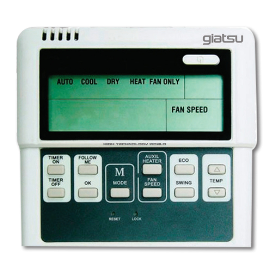
4. Name and function description of LCD screen of wired controller... - Page 8 Table 4-1 Name Function instruction Display when the main unit enter to heating water CIRCULATING Display when the main unit enter to circulating heating water E-HEATING Display when the electric auxiliary heating is operated CHECK Display when press the “Check” key to query parameters Display when the environment temperatue is lower than 2 ANTI-COLD , and it will be canceled when the environment tempera-...
- Page 9 Display the hour and minute, and will change as the CLOCK addition of time, the “ : ” is the second indicating icon; display 24 hours. That displays timing setting. TIMER Display the timer setting a) Display water tank temperature T5 in the initial interface b) Setting water temperature Ts: 40~60 , default value is 56 ;...
-
Page 10: Names Of Keys On The Wired Controller And The Keypad Operation Description
5. Names of keys on the wired controller and the keypad operation description ⑦ ON / OFF BUTTON ① MODE BUTTON ② ⑧ ADJUST BUTTON ▲ TIMER ON BUTTON TIMER FOLLOW ③ TIMER OFF BUTTON ⑨ ADJUST BUTTON ▼ TIMER AUXIL MODE FAN SPEED... - Page 11 When the screen is activated and WATER LEV. unlocked press this key will enter to the This key is used to set the outdoor water timer setting state,if there are no key level. After pressing this key, you can use operations or press the “OK”...
- Page 12 2 on ” setting, the front two of “ ” Normal display —>”Display Timing 1 on (means hour) will be flashed, then can time”—>”Adjust Timing time adjust. Press this key again, he last two of --hour”—>”Adjust Timing 1 on time “...
- Page 13 b. Timing query function temperature TP->Current of compressor A->Current of compressor B->Electric Query through the “Page up” and “Page expansion valve opening->Hot water down” keys. valve opening->Fault->Protection- c. Each on and off time under two >Outlet water temperature T1 timing conditions as follow: RESET (Note: If it is separate setting “On”...
-
Page 14: Error Alarm Handling
40°C~55°C, and the default value for the 6. Error alarm handling unit is 50°C . CYC.TEMP. When the unit fails or the wire controller This key is used to set the inlet tempera- detects failure of communication with the ture of the circulating heating water. After main equipment, the indicator blinks, and pressing this key, you can use the “Increase”... - Page 15 Appendix: Fault code list Table 6-1 Water pressure detection error(Only main unit) Power supply wire phase error Communication error Error of outlet water temperature Error of the water temperature sensor inner the water tank Error of the pipe of condenser temperature Error of a outdoor ambient temperature Error of a electric heater temperature Error of detecting circulating water pressure...
-
Page 16: Technical Indices And Requirements
7. Technical indices and requirements EMC and EMI comply with the CE certification requirements. - Page 17 C./ Industria, 13 l Polígono Industrial El Pedregar 08160 Montmeló Barcelona (Spain) Phone: (0034) 93 390 42 20 Fax: (0034) 93 390 42 05 info@giatsu.com www.giatsu.com...
Need help?
Do you have a question about the GIA-KJR12B and is the answer not in the manual?
Questions and answers