
Related Manuals for Instrumentation GDD GRx8mini

Summary of Contents for Instrumentation GDD GRx8mini
- Page 1 IP RECEIVER Model GRx8mini Instruction Manual 860 boul. de la Chaudière, suite 200 Québec (QC), Canada, G1X 4B7 Tel.: +1 (418) 877-4249 Fax: +1 (418) 877-4054 E-Mail: gdd@gdd.ca Web site: www.gdd.ca...
- Page 2 Visit our web site at: www.gdd.ca Discover GDD’s new products. • Download the latest version of the Instruction Manual. • Comment on or ask questions about products. • Instrumentation GDD Inc. 2018-04-06 Page 2...
-
Page 3: Table Of Contents
8.4.2 Start Recording (raw data) ....................62 Memory Option ......................... 65 8.5.1 Display Reading ........................65 8.5.2 History ..........................66 8.5.3 Back Mem .......................... 67 8.5.4 Clear Mem ......................... 68 8.5.5 Save File ..........................69 About Option ........................73 Instrumentation GDD Inc. 2018-04-06 Page 3... - Page 4 Technical help ........................99 Annex 1 – Geometrical parameters ....................100 Annex 2 – 3D Survey ........................106 Annex 3 – Field survey setup ......................118 Annex 4 – Example Dump File (.gdd format) .................. 140 Instrumentation GDD Inc. 2018-04-06 Page 4...
-
Page 5: Introduction
TFT VGA screen. Before data acquisition, the GRx8mini can be used as a one channel graphic display for monitoring the noise level and checking the primary voltage waveform through a continuous display process. -
Page 6: Receiver Accessories
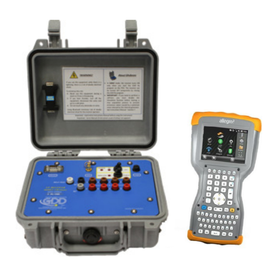
2. Receiver Accessories IP receiver, model GRx8mini UART programming adapter (Boot Loader) Allegro field computer with a 10.6Ah rechargeable Li-Ion battery and an adjustable hand strap Allegro capacitive stylus with tether Allegro Holster case Allegro wall charger with international plug kit... - Page 7 Instrumentation GDD Inc. 2018-04-06 Page 7...
-
Page 8: Receiver Components
3. Receiver Components The GRx8mini components are described in this section. A - RS-232 connector - 9 pin serial communication port This connector is used to connect the serial communication cable between the Allegro the GRx8mini. B - GPS Connector This connector is used to connect an external GPS antenna (SMA). - Page 9 D - ON/OFF switch This switch is used to turn the GRx8mini ON. The ON red light indicates that the GRx8mini is E - FUSE This fuse prevents damages that could be caused by a defective charger. Replacement fuse: 5x20mm 6A 125V fast action F - SELF-TEST terminal This terminal is used to perform a self-test.
- Page 10 (14 pos.) can be purchased and used with the instrument. K - RS-232 external Connector This connector is used to connect the rugged serial communication cable (Amphenol connector), which allows communication between the Allegro and the GRx8mini receiver. Instrumentation GDD Inc. 2018-04-06 Page 10...
-
Page 11: Power
4. Power GDD’s IP Receiver, model GRx8mini, is powered by two internal rechargeable Lithium-ion batteries. The power level of the Rx internal batteries is indicated on the main screen of the Allegro of the GDD Rx software. Here are a few tips for using and storing your lithium-ion powered receiver: Usage •... - Page 12 • If stored for several months, check the battery charge level every six months and recharge them to 50% if they are below 30% charge. Never store fully charged or completely discharged Lithium-Ion batteries for an extended period. Instrumentation GDD Inc. 2018-04-06 Page 12...
-
Page 13: Quick Start Guide
3. Select the communication mode using the CABLE/WIRELESS switch on the GRx8mini panel. In CABLE mode, the red light will turn ON only when the GRx8mini software is active. 4. Connect the rugged serial communication cable (Amphenol connector) between the Allegro (COM1) and the GRx8mini RS-232 external connector (CABLE communication only). - Page 14 F5 for the next acquisitions. Using F5 will skip all configuration and contact resistance windows. If F1 to F5 keystrokes do not work on your Allegro , see Section 12 – Troubleshooting. Instrumentation GDD Inc. 2018-04-06 Page 14...
- Page 15 Displacement enabled Go to Go to next line Go to previous Go to next previous line (or press station station (or (or press F3 F4 keystroke) (or press F1 press F2 keystroke) keystroke) keystroke) Instrumentation GDD Inc. 2018-04-06 Page 15...
- Page 16 14. Click NEXT or press Enter keystroke to continue. *Note: If all stations show an INFINITE contact, the reference electrode might be disconnected. 15. Enter the transmitter current and click CONFIRM or press Enter keystroke to start the readings. Instrumentation GDD Inc. 2018-04-06 Page 16...
- Page 17 Key: “V” or click on the text label directly on the screen. If no transmitter information can be received at the GRx8mini, the following symbol will be displayed instead of I and P: N/A.
- Page 18 “I” value. These are the first “I” transmitted, the average “AI” (with information regarding Standard Deviation “SI” and average time between each Tx values broadcasted “AT”) and the last “I” transmitted. Click on one of the corresponding button. Instrumentation GDD Inc. 2018-04-06 Page 18...
- Page 19 If the REDO POSITIONS option is checked, enter the transmitter and receiver position and click OK or press Enter keystroke. *Each position can be changed individually or moved by clicking Next or Prev (or by using F1 to F4 keystrokes). Instrumentation GDD Inc. 2018-04-06 Page 19...
- Page 20 Down arrows to see all the channels. By clicking on Start, the program will automatically come back to the last acquisition and will start a new acquisition procedure. 21. Repeat steps 9 through 20 to take another set of readings. Instrumentation GDD Inc. 2018-04-06 Page 20...
-
Page 21: Rs232/Bluetooth Communication
6. RS232/Bluetooth Communication Select the “RS-232” communication mode to use the GRx8mini with a serial communication cable. Select the “BLUETOOTH” communication mode to use the GRx8mini with a wireless connection. 3. The following screen appears and you are ready to begin. -
Page 22: Cold Weather And Harsh Environments Tips
1. Never charge the internal batteries of the GRx8mini in sub-zero; 2. As much as possible, turn on the GRx8mini receiver in a warm place before using it in cold weather;... -
Page 23: Tools Menu
Special Use the SPECIAL option to: • Reinitialize the GRx8mini • Test the GRx8mini with the internal simulator • Set signal processing options • Select battery type (if not automatically detected) • Open Port (enables the RF (radio frequency) communication between GDD’s IP transmitter Tx4 and receiver using the optional GDD-RTE01 box. - Page 24 Use the MEMORY option to: • See the History • Recall the previous memory • Clear the memory • Save data in a file About Use the ABOUT option to display the GDD Rx software version number. Instrumentation GDD Inc. 2018-04-06 Page 24...
-
Page 25: Config Option
Pole-Dipole (4/8)* • Pole-Pole (1/32) • Pole-Pole (2/4) • Pole-Pole (2/16)* • Pole-Pole (4/8)* • Gradient (1/32) • Gradient (2/4) • Gradient (2/16)* • Gradient (4/8)* • Wenner • Schlumberger • *For GRx8-32 model only. Instrumentation GDD Inc. 2018-04-06 Page 25... - Page 26 3. Check the active channel(s). Tap on the checkbox to select all channels, or tap on checkbox to unselect all channels. 4. Select the trigger channel, this channel is used for the synchronization process. Instrumentation GDD Inc. 2018-04-06 Page 26...
-
Page 27: Position
The labels N –S and E-W are used to define the direction of the lines. 3. Enter the first electrode position of the transmitter and receiver. A negative number is used to define South and West. Instrumentation GDD Inc. 2018-04-06 Page 27... - Page 28 4. Enter the separation between the electrodes of the receiver. A negative number is used to define South and West. 5. Enter the moving distance of the transmitter and receiver electrodes. A negative number is used to define South and West. Instrumentation GDD Inc. 2018-04-06 Page 28...
-
Page 29: Windows
Use the WINDOWS option to set the signal timing and the mode. 1. Select Tools | Config | Windows. The following screen appears. 2. Select the maximum number of stacks. 3. Select the signal timing. Instrumentation GDD Inc. 2018-04-06 Page 29... - Page 30 80, 80, 80, 80, 80, 80, 80, 80, 80, 80 Semi logarithmic • Windows: 20 Delay (ms): 40 Timing (ms): 2000 40, 40, 40, 40, 40, 40, 80, 80, 80, 80, 80, 80, 80, 160, 160, 160, 160, 160, 160, 160 Logarithmic • Instrumentation GDD Inc. 2018-04-06 Page 30...
- Page 31 120, 220, 420, 820 Cole • Windows: 20 Delay (ms): 20 Timing (ms): 2000 20, 30, 30, 30, 40, 40, 50, 60, 70, 80, 90, 100, 110, 120, 130, 140, 150, 160, 180, 200 Instrumentation GDD Inc. 2018-04-06 Page 31...
- Page 32 In this dialog box, select your file. The Windows window appears automatically. Click OK. The saved values will be loaded in the User defined mode. Click NO to manually enter the delay and window(s) width. Instrumentation GDD Inc. 2018-04-06 Page 32...
- Page 33 Click NO if you do not want to save your User defined settings to a file. In all cases, you will be brought back to this display and the settings you have entered in the User defined window will be loaded into the Allegro field PC. Instrumentation GDD Inc. 2018-04-06 Page 33...
-
Page 34: Synchronization
IMPORTANT: Make sure that your transmitter is also synchronized by GPS before using this option. Note that the GPS synchronization is disabled every time you start the program even if you checked it the last time you used it. Instrumentation GDD Inc. 2018-04-06 Page 34... - Page 35 GPS signal lost for less than 5 hours If you checked Use GPS Time synchronization and if the GPS signal is lost for less than 5 hours, your receiver will still be synchronized with GPS using the internal GPS clock. Instrumentation GDD Inc. 2018-04-06 Page 35...
- Page 36 HV block) and all de Vp will become positive. 6. The .gps output file indicates if the receiver is synchronized with signal or GPS (see Section 8.5 to know how to create a .gps file). Instrumentation GDD Inc. 2018-04-06 Page 36...
- Page 37 IMPORTANT: Even if the file indicates that your receiver is synchronized with the GPS time, it does not confirm that your receiver is well synchronized with your transmitter. In the case that your transmitter and your receiver are not well synchronized together, your data could be erroneous. Instrumentation GDD Inc. 2018-04-06 Page 37...
-
Page 38: Special Option
Please ensure your MEM number is the same than before having reinitialized your GRx8mini. If MEM displays a 0 value, you may need to exit the GDD_Rx software, wait 15 seconds and start the application again. The MEM should be back to its original count. -
Page 39: Simulation
(you need to select the Pole-Pole configuration to use this option). 1. Short the SELF-TEST terminal with the channel(s) you want to test. The picture below shows a self-test testing the first four (4) channels. Instrumentation GDD Inc. 2018-04-06 Page 39... - Page 40 Turn ON the receiver. Select Tools | Config | Setup The following screens appear. Select the Pole-Pole array configuration. Instrumentation GDD Inc. 2018-04-06 Page 40...
- Page 41 Check the channel(s) you want to test. Click Ok. Select Tools | Special | Simulation Enter the waveform timing (default = 2000ms). Enter the primary voltage (default = 500mV). Enter the chargeability (default = 0). Instrumentation GDD Inc. 2018-04-06 Page 41...
- Page 42 It would be a problem if the VP value is not the same during a reading for every channel. For example, a value of 520mV for one channel while you get a value of 503mV for the other ones. Instrumentation GDD Inc. 2018-04-06 Page 42...
-
Page 43: Signal Processing Options
2. Check the checkboxes of the settings you want to disable and click CONFIRM. Note that the gains and offsets are enabled (applied) every time you start the GDD Rx program again even if you disabled them the last time you used them. Instrumentation GDD Inc. 2018-04-06 Page 43... -
Page 44: Battery Type
If the GDD Rx program cannot detect the battery type (older Rx firmware versions), the About pop-up window will indicate Battery Type: not detected. In which case, it is possible to select the battery type manually. Select Tools | Special | Battery Type Instrumentation GDD Inc. 2018-04-06 Page 44... -
Page 45: Open Port
Select the type of batteries in your receiver. All GRx8mini receivers have Li-Ion batteries. If the Battery Type menu is grey (disabled), it means that the battery type is detected by the GDD Rx program and you do not need to set it manually. - Page 46 If the GDD-RTE01 box is not connected or defective, the following message will pop up. Instrumentation GDD Inc. 2018-04-06 Page 46...
-
Page 47: Show Option
Use the shortcut keys to navigate quickly between the different options. The Quick Start option (F5) can be used to start the acquisition procedure using the same settings as the previous acquisition. Using F5 will skip the settings and contact resistance windows. Instrumentation GDD Inc. 2018-04-06 Page 47... -
Page 48: Pseudosection
RESistivity (click on the Pseudosection label to switch between associated to resistivity or chargeability selected Tx / Rx line or use hotkeys ‘E’ and ‘A’) Note: Use the hotkey ‘I’ to invert the Pseudo colors. Instrumentation GDD Inc. 2018-04-06 Page 48... - Page 49 To validate and go back to the pseudosections view, you can either click on « Enter » or on the « OK » button. 4. To visualize the whole pseudosection, use the arrows on the field PC keyboard: Instrumentation GDD Inc. 2018-04-06 Page 49...
-
Page 50: Signal
1. Select Tools | Show | Show Signal Hotkey ‘S’ 2. The following screen appears. Close graph button Channel Selection Time Scale Offset Voltage Scale Graph TOOLS menu Increase Voltage Scale Increase Offset Voltage Decrease Offset Scale Decrease Voltage Scale Instrumentation GDD Inc. 2018-04-06 Page 50... - Page 51 3. Select offset voltage scale. 4. Select time scale. 5. Select display channel. Instrumentation GDD Inc. 2018-04-06 Page 51...
-
Page 52: Tools Menu
This option should be used after one signal period (8 sec for a 2 sec time base). 1. Select Tools | Auto Correction 8.3.3.1.2 Restore The RESTORE option is used to reset the settings to default. 1. Select Tools | Restore Instrumentation GDD Inc. 2018-04-06 Page 52... -
Page 53: Pause/Go
*This option should be used before your transmitter sends a current. If the transmitter sends a current, the Vp signal will be displayed for each active channel. 1. Select Tools | Show | Show Noise Hotkey ‘N’ Instrumentation GDD Inc. 2018-04-06 Page 53... -
Page 54: Vp And Cycle
The current graph is an example; your VP graph will depend on the physical configuration of the electrodes. 1. Select Tools | Show | Show Cycle Hotkey ‘C’ Instrumentation GDD Inc. 2018-04-06 Page 54... -
Page 55: Show M And Errm
• Red dots indicate that the GRx8mini is not synchronized. • Green dots indicate that the GRx8mini is synchronized. • If the GRx8mini is synchronized and the green dots are not moving in the same direction, check the position of the electrodes on the GRx8mini front panel. -
Page 56: Decay Curve
Steps 14 to 16 of Section 5 of this Manual must be done before using this feature. The Decay Curve option is used to display the decay graph of a selected channel. 1. Select Tools | Show | Show Decay Hotkey ‘D’ 2. The following screen appears. Instrumentation GDD Inc. 2018-04-06 Page 56... -
Page 57: Show Windows
The Show Windows option is used to display the chargeability windows of each channel. 1. Select Tools | Show | Show Windows (1-8 ch) Hotkeys ‘1’ (1-8 ch) 2. The following screen appears. Channel number Chargeability value Window number Instrumentation GDD Inc. 2018-04-06 Page 57... -
Page 58: Show Sp
The SHOW SP option is used to display the self-potential (SP) in mV of each channel. 1. Select Tools | Show | Show SP Hotkey ‘P’ 2. The following screen appears. Channel number Self potential value Instrumentation GDD Inc. 2018-04-06 Page 58... -
Page 59: Raw Data Option
Connect an external antenna (SMA) to the GPS connector of the GRx8mini receiver for more efficiency. After turning on the GRx8mini receiver, it can take up to 2 or 3 minutes for the GPS receiver to track and synchronize with a satellite. - Page 60 Once the GPS module is synchronized with a satellite, the following window should appear. This window allows you to verify if the GPS works properly. You can close this window and continue to work normally with your GRx8mini receiver. You can occasionally verify if the GPS is still tracking the satellite.
- Page 61 Date and Hour will be replaced by NO GPS TIME in the .fullwave and .bdf files. Take note that for some reasons, such as weak signal areas, the GPS module will not be able to track and synchronize with a satellite. Instrumentation GDD Inc. 2018-04-06 Page 61...
-
Page 62: Start Recording (Raw Data)
If a pole configuration is selected in the Setup – Config menu, make sure that reference R1 is connected to the ground. If a dipole configuration is selected in the Setup – Config menu, make sure that channel 1 is connected to the ground. Instrumentation GDD Inc. 2018-04-06 Page 62... - Page 63 2. If you want to verify the GPS time, select Check GPS. Instrumentation GDD Inc. 2018-04-06 Page 63...
- Page 64 Tools | Raw data | Stop recording. The extension of the file created with your raw data is ‘.bdf’. This binary format file can be imported and visualized using GDD's IP Post-Processing software. Instrumentation GDD Inc. 2018-04-06 Page 64...
-
Page 65: Memory Option
The following window will appear. The number in the Reading Number field is always the Memory number of the latest reading taken. Enter the number of the reading you want to see. Click on CONFIRM. Select the Windows of chargeability. Click on CONFIRM. Instrumentation GDD Inc. 2018-04-06 Page 65... -
Page 66: History
You will have to use the scroll bar to see all the information available. Click Next to go to the next page. The three following slides show all the information displayed by the history. Instrumentation GDD Inc. 2018-04-06 Page 66... -
Page 67: Back Mem
8.5.3 Back Mem The Back Mem option is used to clear the last readings of the memory one by one. 1. Select Tools | Memory | Back Mem 2. Click Yes to clear the last readings. Instrumentation GDD Inc. 2018-04-06 Page 67... -
Page 68: Clear Mem
The Clear Mem option is used to clear all the readings of the memory. 1. Select Tools | Memory | Clear Mem 2. Click Yes to confirm the operation. 3. Enter 9999 in the text box. Instrumentation GDD Inc. 2018-04-06 Page 68... -
Page 69: Save File
4. Click Confirm to clear all the readings of the memory. 5. A message will follow to confirm your operation. 8.5.5 Save File The Save File option is used to save the readings to a file. 1. Select Tools | Memory | Save File Instrumentation GDD Inc. 2018-04-06 Page 69... - Page 70 4. Select the file location. It is recommended to save your files in the SD Card folder to make sure that you will have enough disk space. Do not save the data in the My Documents folder. Instrumentation GDD Inc. 2018-04-06 Page 70...
- Page 71 If using the GDD-RTE01 communication boxes, an ascii file (gdd_rte.log) will be created at the same location than your IP data. This gdd_rte.log file contains the output current and power values broadcasted by the GDD IP transmitter (model Tx4). Instrumentation GDD Inc. 2018-04-06 Page 71...
- Page 72 _aux at the end of their name. These auxiliary files contain the part of the data that was not saved directly to the compact flash card. You must transfer all these output files from your Allegro field PC to your computer to prevent loss of data. Instrumentation GDD Inc. 2018-04-06 Page 72...
-
Page 73: About Option
8.6 About Option The About option is used to display the software version number. 1. Select Tools | About 2. The following screen appears. *See Section 8.2.4 for more information about Battery Type. Instrumentation GDD Inc. 2018-04-06 Page 73... -
Page 74: Transferring Data
1. Once ActiveSync is installed, a gray icon will appear in the bottom right corner of your desktop PC screen. 2. Right click on the ActiveSync icon to open the following menu and select Connection Settings... Instrumentation GDD Inc. 2018-04-06 Page 74... -
Page 75: Establishing Connection With A Desktop Pc
3. Check Allow USB connection with this desktop computer. 9.1.2 Establishing connection with a desktop PC 1. Turn the PDA ON Instrumentation GDD Inc. 2018-04-06 Page 75... -
Page 76: Transferring File(S) From The Allegro To A Desktop Pc
4. A small PCLink icon appears on the Allegro title bar. 9.1.3 Transferring file(s) from the Allegro to a desktop PC 1. Double click on the My Computer icon on your desktop PC. 2. Double click on the Mobile Device icon. Instrumentation GDD Inc. 2018-04-06 Page 76... - Page 77 If created, the fullwave file is named: File_Name.fullwave See Section 8.5.5 -SAVE FILE for more information about alternate output formats and creating a FULLWAVE file. 5. Open the saved files with Notepad or Excel. Instrumentation GDD Inc. 2018-04-06 Page 77...
-
Page 78: Windows Mobile Device Center
1. Once Windows Mobile Device Center 32 or 64 bits is installed, click the Windows Start Menu icon and then click All Programs to display all installed programs. Click Windows mobile Device Center to launch the application. 2. Under the Mobile Device Settings option, click on Connection settings. Instrumentation GDD Inc. 2018-04-06 Page 78... -
Page 79: Establishing Connection With A Desktop Pc
3. Check Allow USB connections. 9.2.2 Establishing connection with a desktop PC 1. Connect the micro USB cable between the Allegro and the desktop PC. 2. Turn the PDA ON. Instrumentation GDD Inc. 2018-04-06 Page 79... -
Page 80: Transferring File(S) From The Allegro To A Desktop Pc
4. A small PCLink icon appears on the Allegro title bar. 9.2.3 Transferring file(s) from the Allegro to a desktop PC 1. From the Windows Mobile Device Center, click Connect without setting up your device. Instrumentation GDD Inc. 2018-04-06 Page 80... - Page 81 If created, the fullwave file is named: File_Name.fullwave See Section 8.5.5 (SAVE FILE) for more information about alternate output formats and creation of the FULLWAVE file. 5. Open the saved files with Notepad or Excel. Instrumentation GDD Inc. 2018-04-06 Page 81...
-
Page 82: Usb Connection
1. In the main screen of the Allegro , go in the Settings menu. 2. Go in the ''connections'' folder and then select the ''USB to PC option''. 3. Select ''SD Card - Use as external drive (Mass Storage)'' Instrumentation GDD Inc. 2018-04-06 Page 82... - Page 83 4. The Allegro can now be accessed from the Windows File Explorer: Instrumentation GDD Inc. 2018-04-06 Page 83...
-
Page 84: Bluetooth Configuration
2. Tap on the Title bar at the top of the screen to display the pop-up icons and click on the Bluetooth icon. Click on Add new device. Your GDD IP receiver must be on and in wireless mode. Instrumentation GDD Inc. 2018-04-06 Page 84... - Page 85 Enter the passkey 1234, and click Next. The Device Added window appears for a few seconds. Click on Advanced and go to step 8. 1234 Or, click on your device (the serial number of your receiver) to modify its settings. Instrumentation GDD Inc. 2018-04-06 Page 85...
- Page 86 Check Serial Port and click Save. Click on the COM Ports tab and select New Outgoing Port. Select your device (the serial number of your receiver) and click Next. Instrumentation GDD Inc. 2018-04-06 Page 86...
- Page 87 Select COM9 and check Secure Connection. Click Finish. Click OK to close the Bluetooth settings. Instrumentation GDD Inc. 2018-04-06 Page 87...
-
Page 88: Gdd Rx Software Update
3. Double click on the Mobile Device icon. Pictures could be different depending on your computer's operating. 4. Double click on the main directory. (Could be My Handheld PC on another operating system). 5. Double click on the Program Files folder. Instrumentation GDD Inc. 2018-04-06 Page 88... - Page 89 6. Double click on the GDD folder. 7. Delete the old files. Use the drag and drop, or the copy and paste functions to move the new GDD Rx software files from your computer to your Allegro Instrumentation GDD Inc. 2018-04-06 Page 89...
-
Page 90: Troubleshooting
12. Troubleshooting This section suggests problems that could occur while using the GRx8mini and their solutions. For any issues regarding the Allegro field PC other than those related to the GDD program, please refer to the Allegro user manual available on the CD-ROM/USB Stick provided by GDD. - Page 91 If the program still not detects the receiver in Bluetooth mode, open the program in RS232 mode and save all your data. When your data is saved, push and hold the ON button of the Allegro to reset it. Problem: In Bluetooth mode, the following message appears. Instrumentation GDD Inc. 2018-04-06 Page 91...
- Page 92 See Section 10.1 to find out how to verify if a partnership has been established between your receiver and your Allegro Reset your Allegro by pressing and holding the Power button. The following message appears. Select Reset. Problem: A synchronization error message appears while synchronizing with the receiver. Instrumentation GDD Inc. 2018-04-06 Page 92...
- Page 93 You should select the channel that receives the higher signal as the trigger channel. Check if the transmitter works properly. If the transmitted signal is asymmetrical, the receiver may not synchronize. Instrumentation GDD Inc. 2018-04-06 Page 93...
- Page 94 The channels of the receiver are protected against voltage up do 500V but they can read a Vp of up to 15V only. To prevent the voltage saturation, you can try to reduce the transmitted current at the transmitter. Instrumentation GDD Inc. 2018-04-06 Page 94...
- Page 95 Refer to the “Sync PDA on Windows 10.pdf” document located on the CD-ROM/USB Stick provided by GDD. After carrying out a Reinit, the MEM number indicates 0 even though a certain number of acquisitions have already been made. Instrumentation GDD Inc. 2018-04-06 Page 95...
- Page 96 Newer versions of the GDD_Rx software (4.2.43) include an automatic detection and the MEM count should be back to its expected value within a minute or so. A ! sign will appear in front of the MEM number if the SD card is not detected. Instrumentation GDD Inc. 2018-04-06 Page 96...
-
Page 97: Specifications
Up to 1.5 MΩ Signal waveform: Time domain (ON+, OFF, ON-, OFF) Time base: 0.5, 1, 2, 4, 8 and 16 seconds Input impedance: 5 GΩ at 0.125 Hz and 130 MΩ at 7 Hz Instrumentation GDD Inc. 2018-04-06 Page 97... - Page 98 Screen-graphics: decay curves, apparent resistivity, chargeability, Vp, pseudosection 20 programmable chargeability windows One 24 bit A/D converter per channel Internal test generator (Self-test mode) For more details about the Allegro rugged field PC specifications, refer to the Allegro manual. Instrumentation GDD Inc. 2018-04-06 Page 98...
-
Page 99: Technical Help
14. Technical help If you encounter a problem not described in this manual, do not hesitate to contact Instrumentation GDD Inc. for assistance at: Tel.: +1 (418) 877-4249 Fax: + 1 (418) 877-4054 Toll free line: 1-877-977-4249 (in Canada) E-mail: support-technique@gdd.ca... -
Page 100: Annex 1 - Geometrical Parameters
Tx1: Transmitter first electrode position Tx2: Transmitter second electrode position Rx: Receiver first electrode position Sep: Separation between two receiver electrodes Note: For all electrode arrays, the Tx line and the RX line(s) can be different. Instrumentation GDD Inc. 2018-04-06 Page 100... - Page 101 Instrumentation GDD Inc. 2018-04-06 Page 101...
- Page 102 Instrumentation GDD Inc. 2018-04-06 Page 102...
- Page 103 The electrode C1 has to be set far from the other electrodes, usually 5 times the maximum distance between C2 and Pref. The electrodes C1 and Pref have to be set far from C2 and P1, usually 10 times the maximum distance between C2 and P1. Instrumentation GDD Inc. 2018-04-06 Page 103...
- Page 104 Instrumentation GDD Inc. 2018-04-06 Page 104...
- Page 105 The electrodes C1 and C2 are fixed. The electrode P is moved parallel to C inside a zone located in the central part of C1, C2. The electrodes C1, Pref, P1 and C2 are equidistant. The electrodes Pref and P1 are located at the middle point of electrodes C1 and C2. Instrumentation GDD Inc. 2018-04-06 Page 105...
-
Page 106: Annex 2 - 3D Survey
– 6 hole Yellow Line Rx row – 7 hole Yellow Line Rx row – 8 hole Yellow Line Rx row – 9 hole Yellow Line Rx row – 10 hole Yellow Line Rx Instrumentation GDD Inc. 2018-04-06 Page 106... - Page 107 P31-P30 P32-P31 GDD software – Position parameters – Page 1 GDD software – Position parameters – Page 2 GDD software – Position parameters – Page 3 GDD software – Position parameters – Page 4 Instrumentation GDD Inc. 2018-04-06 Page 107...
- Page 108 Pole-Dipole (1/32) INFINITY Line Line Dipole-Dipole (1/32) Line Line Gradient (1/32) Line Line *The transmitter and the receiver can be on the same line. Instrumentation GDD Inc. 2018-04-06 Page 108...
- Page 109 – 6 hole Yellow Line Rx2 row – 7 hole Yellow Line Rx2 row – 8 hole Yellow Line Rx2 row – 9 hole Yellow Line Rx2 row – 10 hole Yellow Line Rx2 Instrumentation GDD Inc. 2018-04-06 Page 109...
- Page 110 P31-P30 P32-P31 GDD software – Position parameters – Page 1 GDD software – Position parameters – Page 2 GDD software – Position parameters – Page 3 GDD software – Position parameters – Page 4 Instrumentation GDD Inc. 2018-04-06 Page 110...
- Page 111 Pole-Dipole (2/16) INFINITY Line Line Line Dipole-Dipole (2/16) Line Line Line Gradient (2/16) Line Line Line *The transmitter and the receiver can be on the same line. Instrumentation GDD Inc. 2018-04-06 Page 111...
- Page 112 – 6 hole Yellow Line Rx4 row – 7 hole Yellow Line Rx4 row – 8 hole Yellow Line Rx4 row – 9 hole Yellow Line Rx4 row – 10 hole Yellow Line Rx4 Instrumentation GDD Inc. 2018-04-06 Page 112...
- Page 113 P31-P30 P32-P31 GDD software – Position parameters – Page 1 GDD software – Position parameters – Page 2 GDD software – Position parameters – Page 3 GDD software – Position parameters – Page 4 Instrumentation GDD Inc. 2018-04-06 Page 113...
- Page 114 Pole-Dipole (4/8) INFINITY Line Line Line Line Line Dipole-Dipole (4/8) Line Line Line Line Line Instrumentation GDD Inc. 2018-04-06 Page 114...
- Page 115 Line Line Line Line Line *The transmitter and the receiver can be on the same line. 4. Receiver Dipole (2/4) – For GRx8mini only Line Rx1 Line Rx2 Electrode number (software Electrode position on the Electrode color on the Electrode line number...
- Page 116 P2-P1 P3-P2 P4-P3 P5-PR2 P6-P5 P7-P6 P8-P7 GDD software – Position parameters – Page 1 GDD software – Position parameters – Page 2 Pole-Dipole (2/4) INFINITY Line Line Line Dipole-Dipole (2/4) Line Line Line Instrumentation GDD Inc. 2018-04-06 Page 116...
- Page 117 Gradient (2/4) Line Line Line *The transmitter and the receiver can be on the same line. Instrumentation GDD Inc. 2018-04-06 Page 117...
-
Page 118: Annex 3 - Field Survey Setup
Annex 3 – Field survey setup Survey setup Line information This survey consists of 11 lines, each separated by 100m. Each line is 1.3 km long. The examples below will begin at position 3300N-3900E. Instrumentation GDD Inc. 2018-04-06 Page 118... - Page 119 Pole-Pole For this pole-pole setup, 8 electrodes of the GDD-Rx will be used. 1) Select Pole-Pole in the setup page. Instrumentation GDD Inc. 2018-04-06 Page 119...
- Page 120 3) If all the values are correct, click the Ok button to continue and take a reading. If something is incorrect, you can modify it on this page. 4) When the reading is done, click the NEXT STN button to increment the positions. Instrumentation GDD Inc. 2018-04-06 Page 120...
- Page 121 For this pole-dipole setup, 8 electrodes of the GDD-Rx will be used. 1) Select Pole-Dipole (1/32) in the setup page. The Pole-Dipole (2/16) and Pole-Dipole (4/8) options are explained in the 3D survey section at the end of this document. Instrumentation GDD Inc. 2018-04-06 Page 121...
- Page 122 3) If all the values are correct, click the Ok button to continue and take a reading. If something is incorrect, you can modify it on this page. 4) When the reading is done, click the NEXT STN button to increment the positions. Instrumentation GDD Inc. 2018-04-06 Page 122...
- Page 123 Dipole-Dipole (1/32) For this dipole-dipole setup, 8 electrodes of the GDD-Rx will be used. 1) Select Dipole-Dipole (1/32) in the setup page. Instrumentation GDD Inc. 2018-04-06 Page 123...
- Page 124 3) If all the values are correct, click the Ok button to continue and take a reading. If something is incorrect, you can modify it on this page. 4) When the reading is done, click the NEXT STN button to increment the positions. Instrumentation GDD Inc. 2018-04-06 Page 124...
- Page 125 Gradient (1/32) For this Gradient setup, 8 electrodes of the GDD-Rx will be used. 1) Select Gradient (1/32) in the setup page. Instrumentation GDD Inc. 2018-04-06 Page 125...
- Page 126 Only the Receiver electrodes position changes. In this example, you will need to click the NEXT STN button 8 times to be at the position indicated on the next screen. Instrumentation GDD Inc. 2018-04-06 Page 126...
- Page 127 5) Your next setup on the field should be like this. Wenner A Wenner setup uses only two electrodes, the Reference R1 and the electrode 1 of the GDD Rx. 1) Select Wenner in the setup page and check only one channel. Instrumentation GDD Inc. 2018-04-06 Page 127...
- Page 128 4) For a Wenner survey, you will have to manually enter the parameters for each reading. To access the Position page, click the Tools button and select the Config option in the pop-up menu. Instrumentation GDD Inc. 2018-04-06 Page 128...
- Page 129 Schlumberger A Schlumberger setup uses only the Reference R1 and the electrode 1 of the GDD Rx. 1) Select Schlumberger in the setup page. Instrumentation GDD Inc. 2018-04-06 Page 129...
- Page 130 4) For a Schlumberger survey, you will have to manually enter the parameters for each reading. To access the Position page, click the Tools button and select the Config option in the pop-up menu. Instrumentation GDD Inc. 2018-04-06 Page 130...
- Page 131 3D Survey: Pole-Dipole (2/16) Instrumentation GDD Inc. 2018-04-06 Page 131...
- Page 132 GDD Rx-32. For the reference pins, R1 and R3 will be used; R2 and R4 will not be used since this is a 2 lines setup. 1) Select the Pole-Dipole 2/16 on the Setup tab. 2) On the Position tab; enter the parameters of your survey. Instrumentation GDD Inc. 2018-04-06 Page 132...
- Page 133 4) After readings are taken and stored, click the Start button. Click the NEXT STN button and only the Tx2 station will be incremented by 100 since it was entered as the Tx spacing. Instrumentation GDD Inc. 2018-04-06 Page 133...
- Page 134 6) Continue the survey. When the Tx2 station position is at 1200, you will have to change the spacing back to 100. 7) When the line is complete press NEXT LINE to increment the LTx. Instrumentation GDD Inc. 2018-04-06 Page 134...
- Page 135 8) When the line is done, change the Move ST.: TX: to -100 or the Tx2 position to 0 depending on where you are starting the next line. 3D survey: Gradient (4/8) Instrumentation GDD Inc. 2018-04-06 Page 135...
- Page 136 3) If all the values are correct, click the Ok button to continue and take a reading. If something is incorrect, you can modify it on these pages. Uncheck the Tx box so that only the Receiver electrodes position will change. Instrumentation GDD Inc. 2018-04-06 Page 136...
- Page 137 Only the electrodes position on the Receiver will change. In this example, you will need to click the NEXT STN button 8 times to be at the position indicated on the next screen. Instrumentation GDD Inc. 2018-04-06 Page 137...
- Page 138 5) Your next setup on the field should be like this. Instrumentation GDD Inc. 2018-04-06 Page 138...
- Page 139 Instead of using a relative position system (the starting position being 0,0), you can enter a GPS position in meters in the Line TX, Line RX, Tx1, Tx2 and Station Rx cases. You can enter any number between -9999999 and 9999999. Next Station Next Line Instrumentation GDD Inc. 2018-04-06 Page 139...
-
Page 140: Annex 4 - Example Dump File (.Gdd Format)
• Each line in section 4 has a fix number of entries. If less than 20 windows are defined for a selected entry, the unused columns will be padded with 999.99 • The example file is truncated on the right side omitting column M02 to M20 Instrumentation GDD Inc. 2018-04-06 Page 140... - Page 141 Error of M: standard deviation of the data set used to calculate the changeability Current in mA Time Transmitter timing in ms Duty Cycle in % Stack Number of stacks M01 – M20 Windows of chargeability Instrumentation GDD Inc. 2018-04-06 Page 141...
Need help?
Do you have a question about the GRx8mini and is the answer not in the manual?
Questions and answers