AGS Merlin 2000S Installation & Operation Manual
Gas proving and ventilation interlock system
Hide thumbs
Also See for Merlin 2000S:
- User manual (12 pages) ,
- Installation & operation manual (12 pages)
Table of Contents
Advertisement
Quick Links
Installation & Operation Manual
This panel is designed for use when the kitchen appliances do not have flame failure devices fitted, therefore gas
proving is a requirement.
The Merlin 2000S system acts as an interlock between the ventilation system and the gas solenoid v alve. The
system is compatible with both current monitors and air pressure differential switches in order to interlock with up
to 4 fans.
The information contained within this manual should be referenced for typical installation and operation only.
For specific requirements that may deviate from the information in this guide – contact your supplier.
Rev: 10
02-21
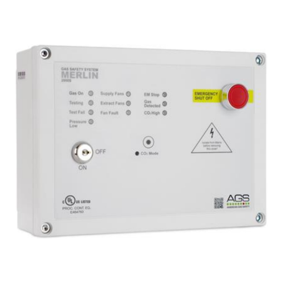
Merlin 2000S
Gas Proving and Ventilation interlock system
Installation & Operation Manual
Please read this manual carefully and retain for future use.
Merlin 2000S
1
Advertisement
Table of Contents

Related Manuals for AGS Merlin 2000S


Summary of Contents for AGS Merlin 2000S
- Page 1 The Merlin 2000S system acts as an interlock between the ventilation system and the gas solenoid v alve. The system is compatible with both current monitors and air pressure differential switches in order to interlock with up to 4 fans.
-
Page 2: Table Of Contents
Installation & Operation Manual Merlin 2000S Contents IMPORTANT WARNING STATEMENTS ............3 Installation ....................4 Planning ........................4 Fixing - Mounting ......................4 Typical Installation Arrangement ................. 5 Terminal Connections ....................5 Switch Settings ......................7 Specification ........................ 8 Operation ....................9 First Power Up ...................... -
Page 3: Important Warning Statements
Please contact your supplier or local authority for details of recycling schemes in your area. Alternatively, all AGS products can be securely packaged and returned clearly marked for disposal. Rev: 10 02-21... -
Page 4: Installation
The fans can be monitored through air pressure switches or by means of an additional current monitor. To operate the Merlin 2000S the fans should be turned to the ‘on’ position, once the panel receives a signal to indicate the fans are operating the key on the panel can be turned to the ‘on’ position and this will open the gas solenoid valve. -
Page 5: Typical Installation Arrangement
Installation & Operation Manual Merlin 2000S Typical Installation Arrangement Terminal Connections 1. POWER / LINE IN 110-120V AC Power should be supplied to the [POWER / LINE IN] terminal and fused at 3A. On connecting the mains supply to the panel the power LED indicator will light up – this is located on the front cover (American Gas Safety Logo). - Page 6 Connections for remote emergency shut-off or stop buttons is detailed on the circuit board as [EM REMOTE]. This is linked out as a factory setting. Remote emergency shut-off buttons should be volt free and wired to the Merlin 2000S using a plenum security cable, white, 18/2 (18AWG 2 conductor), stranded, CMP or similar.
-
Page 7: Switch Settings
Fire Panel Integration The Merlin 2000S can be integrated with a fire alarm to close the gas supply automatically in the event of a fire. The volt free fire alarm signal can be wired in series with any remote emergency shut off buttons. -
Page 8: Specification
Installation & Operation Manual Merlin 2000S MODE Under normal working conditions the Merlin 2000S monitors the ventilation and the concentration level of Carbon Dioxide (CO ) in the air In the event of ventilation failure or if the CO level is at alarm level, the panel will shut off the gas supply. -
Page 9: Operation
LED Indicators Gas On When the fans are running and the key switch is turned on, the Merlin 2000S will open the gas valve and the Gas-On LED will illuminate. ON = Gas On / OFF = Gas Off ... -
Page 10: Co 2 Mode
Mode, this button has to be pressed for 5 seconds. The Fan Fault LED will go off and CO Mode LED will come on. In this mode, the Merlin 2000S will monitor only the CO levels to ensure there is a safe working environment and allow the gas valve to open for 8 hours each time CO2 Mode is activated provided CO levels are safe. -
Page 11: Maintenance
What equipment do I need to perform a Bump Test? Contact your AGS representative for details of suitable bump testing kits and gases. Kits usually consist of a certified gas cylinder; flow control regulator, tube pipe and applicator cone. - Page 12 Installation & Operation Manual Merlin 2000S Installation Details Please pass this manual to the system owner or system user. Date of Installation: Installation Location: Organisation: Stamp/ Signature of the installer: American Gas Safety LLC Head office: 6304 Benjamin Road, Suite 502, Tampa, FL 33634 Tel: (727) 608-4375 info@americangassafety.com...
Need help?
Do you have a question about the Merlin 2000S and is the answer not in the manual?
Questions and answers