Table of Contents
Advertisement
1.
SAFETY PRECAUTIONS AND WARNINGS .............................................. 1
2.
GENERAL INFORMATION .......................................................................... 2
2.1
2.2
2.3
2.4
2.5
2.6
2.7
3.
USING THE SCAN TOOL ............................................................................ 10
3.1
3.2
3.3
3.4
3.5
3.6
3.7
3.8
3.9
V
4.
OBDII DIAGNOSTICS ................................................................................. 24
4.1
4.2
4.3
4.4
V
4.5
4.6
V
4.7
5.
READY TEST ................................................................................................ 41
5.1
5.2
5.3
6.
WARRANTY AND SERVICE ...................................................................... 46
6.1
6.2
Table of Contents
.................................................................................... 6
.................................................................................... 10
.......................................................................................... 11
.................................................................................................. 12
........................................................................................................ 12
............................................................................................ 12
......................................................................................................... 21
.................................................................................. 21
......................................................................................... 25
.......................................................................................... 28
.................................................................................................. 30
V
................................................................................ 46
(OBD) II ............................................................. 2
) ........................................................ 2
.................................................................... 4
......................................................... 5
.................................................................... 7
............................................................................. 11
........................................................................ 12
.................................................................... 22
................................................................. 31
......................................................... 32
.............................................................. 39
.......................................................................... 40
............................................................................ 41
............................................................................ 41
.............................................................. 44
................................................................ 46
(DLC) .................................... 3
Advertisement
Table of Contents

Related Manuals for JDiag JD201


Summary of Contents for JDiag JD201
-
Page 1: Table Of Contents
Table of Contents SAFETY PRECAUTIONS AND WARNINGS ..........1 GENERAL INFORMATION ................2 (OBD) II ............. 2 OARD IAGNOSTICS (DTC ) ............2 IAGNOSTIC ROUBLE ODES (DLC) ........3 OCATION OF THE ONNECTOR OBD II R ..............4 EADINESS ONITORS OBD II M ............ -
Page 2: Safety Precautions And Warnings
1. Safety Precautions and Warnings To prevent personal injury or damage to vehicles and/or the scan tool, read this instruction manual first and observe the following safety precautions at a minimum whenever working on a vehicle: Always perform automotive testing in a safe environment. ... -
Page 3: General Information
2. General Information 2.1 On-Board Diagnostics (OBD) II The first generation of On-Board Diagnostics (called OBD I) was developed by the California Air Resources Board (ARB) and implemented in 1988 to monitor some of the emission control components on vehicles. As technology evolved and the desire to improve the On-Board Diagnostic system increased, a new generation of On-Board Diagnostic system was developed. -
Page 4: Location Of The Data Link Connector (Dlc)
DTC Example P 0 2 0 2 Systems B=Body Identifying specific C=Chassis malfunctioning P=Powertrain section of the U=Network systems Code Type Sub-systems 1= Fuel and Air Metering Generic (SAE): P0, P2, P34-P39 2= Fuel and Air Metering B0, B3 3= Ignition System or Engine Misfire C0, C3 4= Auxiliary Emission Controls U0, U3. -
Page 5: Obd Ii Readiness Monitors
the connector. If the DLC cannot be found, refer to the vehicle‟s service manual for the location. 2.4 OBD II Readiness Monitors An important part of a vehicle‟s OBD II system is the Readiness Monitors, which are indicators used to find out if all of the emissions components have been evaluated by the OBD II system. -
Page 6: Obd Ii Monitor Readiness Status
operated under specific conditions before the monitor is ready. These monitors are termed non-continuous monitors. For different ignition type engines, the available monitors are different too. The following monitors are to be used for spark ignition engines only: EGR System O2 Sensors Catalyst Evaporative System... -
Page 7: Obd Ii Definitions
or “Complete”, it will remain in this state. A number of factors, including erasing of diagnostic trouble codes (DTCs) with a scan tool or a disconnected battery, can result in Readiness Monitors being set to “Not Ready”. Since the three continuous monitors are constantly evaluating, they will be reported as “Ready”... -
Page 8: Obd Ii Modes Of Operation
require the vehicle to follow a prescribed “drive cycle” routine as part of the enabling criteria. Drive cycles vary among vehicles and for each monitor in any particular vehicle. OBD II Drive Cycle -- A specific mode of vehicle operation that provides conditions required to set all the readiness monitors applicable to the vehicle to the “ready”... - Page 9 Mode $02 - Displays Freeze Frame data. Same data as in mode 1, but it was captured and stored when a malfunction occurred and a DTC was set. Some of the PIDs for mode one are not implemented in this mode. Mode $03 - Displays the type of powertrain or emission related DTCs stored by a 5 digit code identifying the faults.
- Page 10 used by service technicians to verify repair was performed properly and after clearing diagnostic trouble codes. Mode $08 - This Special Control Mode requests control of the on-board system, test, or component bi-directionally (where applicable). This mode is manufacturer specific. Mode $09 - Reports vehicle information.
-
Page 11: Using The Scan Tool
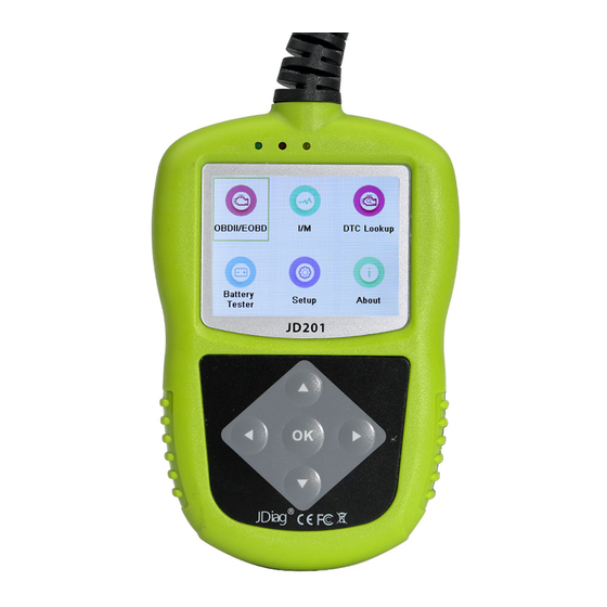
3. Using the Scan Tool 3.1 Tool Description ① OBD II CONNECTOR – Connects the scan tool to the vehicle‟s Data Link Connector (DLC). ② YELLOW LED – Indicates there is a possible problem. A “Pending” DTC is present and/or some of the vehicle‟s emission monitors have not run their diagnostic testing. -
Page 12: Specifications
RED LED – Indicates there is a problem in one or more of ④ the vehicle‟s systems. The red LED is also used to show that DTCs are present. DTCs are shown on the Scan Tool‟s display. In this case, the MIL lamp on the vehicle‟s instrument panel will light steady on. -
Page 13: Navigation Characters
OBD2 cable -- Provides power to tool and communicates between tool and vehicle. USB cable -- Allows easy update via a PC and an internet connection. 3.4 Navigation Characters Characters used to help navigate the scan tool are: “#” -- Identifies the control module number from which data is retrieved. - Page 14 Tool Self-test: Checks if the LCD display, LED lamps and keyboard are working normally. Update Mode: Accesses the Update Mode. Settings of the unit will remain until change to the existing settings is made. To enter the Setup menu When the scan tool is powered on, it displays a Main Screen.
- Page 15 Language Setup English is the default language. From System Setup screen, use the Direction button to select Language, and press the OK button. Use the Direction button to select the desired language and press the OK button to save your selection and return to previous screen.
- Page 16 Allowed INC Monitors From Configure Monitors screen, use the Direction button to select Allowed INC Monitors, and press the OK button. Emissions tests vary depending on the geographic or regional area in which the vehicle is registered. So the scan tool provides a more flexible way to meet different standards, which allows the user to select 0, 1, 2, 3 „not complete‟...
- Page 17 Unit of Measure English Metric Figure 3.5 Press the OK button to save your selection and return to previous menu. Key Beep Set This function allows you to turn on/off the build-in speaker for key pressing. The default setting is Beep On. From System Setup screen, use the Direction button to select Key Beep Set and press the OK button.
- Page 18 Status Beep Set The default setting is Beep On. This function allows you to turn on/off the build-in speaker for the LEDs in diagnostic testing. Different audio tone corresponds to different LED lamp. This function is invaluable when working in bright areas where LED illumination alone is not sufficient.
- Page 19 Select Display Test from Tool Self-test menu and press the OK button to start test. Tool Self-test Display Test Keyboard Test LED Test Previous Menu Figure 3.8 Look for missing spots in the red, green, blue, black and white LCD display. When completed, press the OK button to exit.
- Page 20 A PC or laptop with USB ports A USB cable Download the programs to be updated to your computer. Run JDiag update Tool Kit in your computer. (Figure 3.11) Connect the scan tool to your computer through the USB cable provided.
- Page 21 Select the programs to be updated in your computer. There are two types of programs: operating system and DTC library. (Figure 3.11) Click Update in the JDiag update Toolkit window to begin updating. Figure 3.11 During the update procedure, the scan tool displays a message “Update Program.
-
Page 22: About
View tool information on screen. 3.9 Vehicle Coverage The JDiag JD 201 OBDII/EOBD Scanner is specially designed to work with all OBD II compliant vehicles, including those equipped with next-generation protocol -- Control Area Network (CAN). It is... -
Page 23: Product Troubleshooting
compliant, check the Vehicle Emissions Control Information (VECI) Label which is located under the hood or by the radiator of most vehicles. If the vehicle is OBD II compliant, the label will designate “OBD II Certified”. Additionally, Government regulations mandate that all OBD II compliant vehicles must have a “common”... - Page 24 Run the LED Test in the System Setup menu. (see 3.7 System Setup). If the scan tool did not pass this test, there is a problem with the LED lamp. Please contact JDiag Tech Support or your local selling agent.
-
Page 25: Obdii Diagnostics
4. OBDII Diagnostics When more than one vehicle control module is detected by the scan tool, you will be prompted to select the module where the data may be retrieved. The most often to be selected are the Power train Control Module [PCM] and Transmission Control Module [TCM]. -
Page 26: Reading Codes
7) View a summary of system status (MIL status, DTC counts, Monitor status) on screen. (Figure 4.1 ) Wait a few seconds or press any key for Diagnostic Menu (Figure 4.3) to come up. System Status Codes Found Ignition Type Spark Monitors N/A Monitors OK... - Page 27 the control module to illuminate the malfunction indicator light (MIL) when emission-related fault occurs. Pending Codes are also referred to as “maturing codes” or “continuous monitor codes”. They indicate problems that the control module has detected during the current or last driving cycle but are not considered serious yet.
- Page 28 Read Codes Stored Codes Pending Codes Permanent Codes Previous Menu Figure 4.4 If there is not any Diagnostic Trouble Code, the display indicates “No (pending) codes are stored in the module!” Wait a few seconds or press any key to return to previous screen.
-
Page 29: Erasing Codes
Press any key to select vehicle make!” message comes up prompting you to select vehicle manufacturer to view DTC definitions. Use Direction button to select manufacturer and then press OK button to confirm. Vehicle Manufacturer 1/28 BUICK CADILLAC CHEVROLET CHRYSLER FORD Figure 4.6 ... - Page 30 1) Use the Direction button to select Erase Codes from Diagnostics Menu and press the OK button. (Figure 4.3) 2) A warning message comes up asking for your confirmation. Erase Codes Erase trouble codes! Are you sure? Figure 4.7 If you do not want to proceed with erasing codes, use Direction button to select NO to exit.
-
Page 31: Live Data
Erase Codes Erase Failure. Turn Key on with Engine Off! Press any key to con. Figure 4.9 4.3 Live Data The function allows viewing of live or real time PID data of vehicle’s computer module(s). 1) To view live data, use the Direction button to select Live Data from Diagnostic Menu and press the OK button. -
Page 32: Viewing Freeze Frame Data
…………………View Data 1/3. Complete Data Set Unit of Measure Previous Menu Figure 4.11 4) View live PIDs on the screen. Use the Direction button for more PIDs if additional information is available on more than one page. Live Data DTC_CNT FUELSYS1 FUELSYS2 LOAD_PCT (%) -
Page 33: Retrieving I/M Readiness Status
(VSS) etc. This information will aid the technician by allowing the parameters to be duplicated for diagnostic and repair purposes. To view freeze frame data, use the Direction button to select View Freeze Frame from Diagnostic Menu and press the OK button. - Page 34 complete drive cycle with no trouble codes in memory. Times for reset vary depending on vehicle. Some latest vehicle models may support two types of I/M Readiness tests: A. Since DTCs Cleared - indicates status of the monitors since the DTCs are erased.
- Page 35 Figure 4.14 “Green” -- Indicates that a particular monitor being checked has completed its diagnostic testing. “Red ” -- Indicates that a particular monitor being checked has not completed its diagnostic testing. “Gray” -- The monitor is not supported on the vehicle. The green, yellow and red LEDs provide a quick way to help you determine if a vehicle is ready for an Emission Test.
- Page 36 If a “Stored” Diagnostic Trouble Code is causing the Yellow LED to light, it is still possible that the vehicle will be allowed to be tested for emissions and certified. If a “Pending” Diagnostic Trouble Code is causing the Yellow LED to light, it is still possible that the vehicle will be allowed to be tested for emissions and certified.
- Page 37 Take the vehicle to a professional to have it serviced. The problem(s) causing the red LED to light must be repaired before the vehicle is ready for an Emissions Test. Audio Tone Interpretation The audio tone is configured according to the I/M Readiness Status. This function is invaluable when performing diagnostics and driving at the same time, or working in bright areas where LED illumination alone is not sufficient.
- Page 38 ……………I/M Readiness 1/2. Since DTCs Cleared This Drive Cycle Figure 4.15 4) Use the Direction button, as necessary, to view the status of the MIL light (“ON” or “OFF) and the following monitors. For spark ignition engines: MIS -- Misfire Monitor ...
- Page 39 …………Since DTCs Cleared MIL Status Misfire Monitor Fuel System Mon Comp. Component Catalyst Mon Htd Catalyst Figure 4.16 5) If the vehicle supports readiness test of “This Drive Cycle”, a screen of the following displays: …………..This Drive Cycle MIL Status Misfire Monitor Fuel System Mon Comp.
-
Page 40: Viewing Vehicle Information
4.6 Viewing Vehicle Information The Vehicle Info. function enables retrieval of Vehicle Identification (VIN), Calibration Nos. (CINs), Calibration Verification Nos. (CVNs) and In-use Performance Tracking on 2000 and newer vehicles that support Mode 9. 1) Use Direction button to select Vehicle Info. from the Diagnostic Menu and press OK button. -
Page 41: Exiting The Obdii Test
Vehicle Info. Vehicle ID Number Calibration ID Cal. Verf. Number Previous Menu Figure 4.20 5) View retrieved vehicle information on screen. Cal. Verf. Number CVN1: BB BA A0 78 Figure 4.21 6) Select Previous Menu from the Vehicle Info screen, and press OK button to return to the previous menu. -
Page 42: Ready Test
5. Ready Test This function can be used as a convenient readiness test tool by automotive technicians to determine if the tested vehicle is ready for an emission test. By visual and audible indication, you will learn a vehicle’s monitors readiness. 5.1 General Information Repairs to the emissions-control systems of a 1996 or newer vehicle cause the vehicle‟s computer (ECU) memory to be cleared. - Page 43 The purpose of this function is to indicate which of the vehicle‟s monitors have run and completed their diagnosis and testing, and which ones have not yet run and completed testing and diagnosis of their designated sections of the vehicle‟s emission system. All data shows on one screen, which provides a simple profile of vehicle at a glance, saving diagnosis time and improving technician productivity.
- Page 44 After the erase procedure is performed, status of most monitors will be changed. Leave the scan tool connected to the vehicle, and select Ready Test from Main Screen. Keep on driving the car till the scan tool notifies you safely with color LEDs and audible tone that the drive cycle has been completed and the vehicle is ready, eliminating drive cycle guesswork and confirming readiness status.
-
Page 45: Led And Tone Interpretation
NOTE: This function reads off the real time data of emission-related monitoring systems readiness status. Once the scan tool has finished other operations, for example, clearing trouble codes, the I/M Readiness Monitor Status program resets status of all the monitors to “INC” condition. In order to set these monitors to a Ready status, the vehicle must be driven through a complete drive cycle. - Page 46 “GRAY” -- The monitor is not supported on the vehicle. The LED and audio tone indications are interpreted as below: LED Interpretation The green and red LEDs provide an easy way to check if emission-related monitoring systems complete their self-diagnostic testing.
-
Page 47: Warranty And Service
6. Warranty and Service 6.1 Limited One Year Warranty JDiag warrants to its customers that this product will be free from all defects in materials and workmanship for a period of one (1) year from the date of the original purchase, subject to the following terms and... - Page 48 JDiag Technology Inc. All Rights Reserved. www.jdiag.com V1.00 | 12/2016...
Need help?
Do you have a question about the JD201 and is the answer not in the manual?
Questions and answers