
Summary of Contents for Diagon Coag2D
- Page 1 semi-automated coagulometer User Manual Reference No.: 11000102EN Internal Reference No.: DIAB102AEN...
- Page 2 This document applies to the latest software version listed and higher versions. When a subsequent software version changes the information in this document, a new electronic edition is released and supplied by Diagon Ltd. Copyright © 2018. ALL RIGHTS RESERVED. DIAGON Ltd...
-
Page 3: Table Of Contents
Table of Contents 1. Introduction 1.1. Legal Information ......6 1.2. Limited Warranty ......6 2. - Page 4 12.1 Filter ........34 12.2 Detailed Display .
-
Page 5: Introduction
1. Introduction Thank you for choosing Diagon by purchasing our product, the Coag 2D semi-automated coagulometer. The Coag 2D is a 2-channel semi-automated coagulation analyzer made for in vitro diagnostic use. The Coag 2D is capable of analyzing blood samples with great accuracy. The instrument is suitable for detecting... -
Page 6: Legal Information
Those who lack such experience may only use the product under direct supervision of representatives of Diagon Ltd. Diagon Ltd. will not take responsibility for any damage or loss that result from, or are in connection with the actions of persons who did not receive full training from Diagon Ltd. -
Page 7: Package And Accessories
2. Package and Accessories Make sure all items listed are present in the package when unboxing. Coag 2D analyzer 1 pc. Power supply unit 1 pc. Magnetic mixer (2 pcs / set) 1 set User Manual (this document) 1 pc... -
Page 8: List Of Symbols
3. List of Symbols 3.1 Data Table Symbols Serial Number Catalogue Number In Vitro Diagnostic Device CE Conformity Read the Manual Manufacturer information Requires specific disposal 3.2 Symbols on Accessories Single use only Non-sterile Sufficient for n uses... -
Page 9: Symbols On The Packaging
3.3 Symbols on the Packaging Fragile Keep Dry Proper Storage Suitable Temperature Range Suitable Humidity Range... -
Page 10: Safety Guidelines
(such as reagents, cleansers and cuvettes). For the list of manufacturer approved consumables, visit the official Diagon website (www.diagon.com). Compliance with this manual is also part of the conditions of intended use – make sure to follow these instructions regarding cleaning and mainte- nance procedures to prevent any issues that may arise while operating the Coag 2D. -
Page 11: Placement Of The Coag 2D
Avoid spilling samples, reagents or any liquids into the instrument as fore- ign objects and liquids may cause the instrument to short circuit or to set on fire. In the case spillage does happen and it disrupts the function of the instrument, hit the main switch and disconnect the power cord immedia- tely. -
Page 12: Accident And Injury Prevention
Only connect the Coag 2D into a wall socket with appropriate grounding with a power cord that complies with local standards. 4.5 Accident and Injury Prevention Always follow your local safety regulations when operating the Coag 2D. The external barcode reader of the Coag 2D emits low energy laser radia- tion, looking directly into them may cause eye pain or permanent damage to the eye. -
Page 13: Reagent Safety Guide
For further information on the use of reagents, refer to the instructions for use packaged with them or the official Diagon website (www.diagon. com). Please note that the product selection may be subject to change – always obtain the most current information regarding the reagents from... -
Page 14: Technical Description Of The Coag 2D
Diagon Ltd. or the authorized distributor. The Coag 2D is suitable for analyzing the following parameters:... - Page 15 increases until complete coagulation takes place. Coagulation time starts when the reaction mixture is prepared, and its completion can be determined from the time function of the intensity of the light scattering. The algorithm is in the Setup menu, which plays a role in the determina- tion of the endpoint of the coagulation time.
- Page 16 cubated for a specified amount of time. The immunology reagent is then dispensed into the sample, which creates optical turbidity by the antibo- dy-antigen binding complex. This changes the light intensity at a certain wavelength, and such change is proportional to the concentration of the reaction mixture.
-
Page 17: Specifications
density (OD) is measured. After a few minutes have elapsed, a second measurement takes place, after which the two ODs measured are com- pared in terms of light intensity change, which is given in OD/min. Chromogenic Test Result Calculation: Percentage: The percentage value is calculated form the transmitted light intensity change per minute (OD/min). -
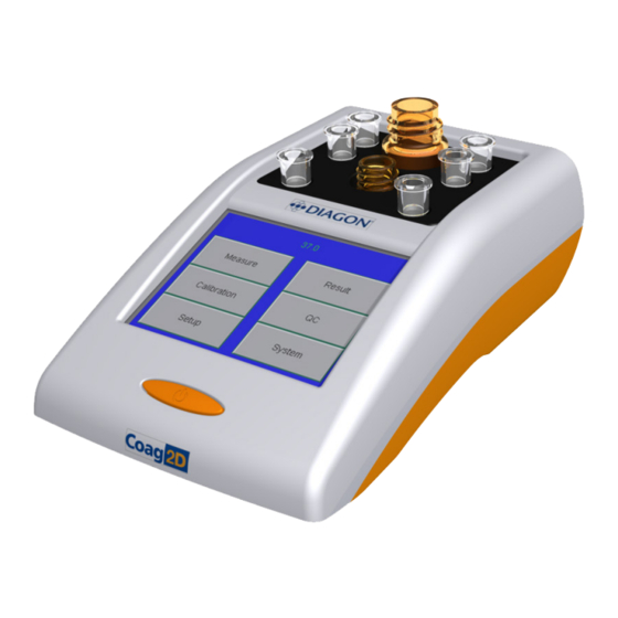
Page 18: Components Of The Coag 2D
6. Components of the Coag 2D 6.1 Structure of the Instrument Figure 6.1 - Top overview On/Off switch – for powering the instrument on and off. Display – A color graphic liquid crystal touchscreen for operating and navigating in the analyzer software. Incubation Area - The incubation area is a monolithic aluminium block regulated to 37 °C. - Page 19 Status indicators – located on the lower part of the screen. Used for monitoring the status of measurement position Figure 6.2 - Rear overview External power supply connector - GTM41060-182509GTM21097-4509 type power supply unit, with input voltage 100-240V AC, and output vol- tage.
-
Page 20: Installation Of The Coag 2D
7. Installation of the Coag 2D 7.1 Installation Requirements Place the instrument on a horizontal laboratory table. It requires an empty space at least 300x300mm in size. Place the instrument near a grounded mains power connector that has a maximum of 1.5 A input current. Place the instrument in a way that the power cord can be easily disconnected if necessary. - Page 21 Check whether the display is fully functional by tapping any button on screen. The content displayed depends on the item selected. To return to the main menu, tap the Esc button. Check whether the date and time displayed are correct. In case they are not, set them in the ‘System’...
-
Page 22: Setup Menu
Editing privileges are in effect until the instrument is switched off. The default password is provided by the Diagon authorized distributor or service engineer. To save changes, tap the tick button. To discard changes, tap the X but- ton. -
Page 23: Setup Of Nephelometric Test Parameters
8.1 Setup of Nephelometric Test Parameters Min. Time Sets the minimum amount of time that may be measured. If the reaction time is below this value, the result will be marked with a T flag. Max. Time Sets the maximum amount of time that may be measured. If the instru- ment does not detect the endpoint of the reaction, it stops the measure- ment and the result will be marked with a T flag. -
Page 24: Setup Of Turbidimetric And Chromogenic Test
Parallel Measurements can be performed on two channels in order to reduce imp- recisions that may result from manual pipetting. When the discrepancy between the results is within a certain percentage range, the device cal- culates the average of the two results, and if the discrepancy is out of range, the result will be flagged with a ‘D’. -
Page 25: System Menu
9. System Menu Tap the ‘System’ button to access the system settings menu. The current software version and the serial number of the instrument are displayed at the top of the screen. Figure 9.1 - System menu 9.1 Available Options Language: English Polish... -
Page 26: Error Messages
waiting period is required. For more detailed information on connecting external devices to the instrument, see section 6.1. Note: it is recommended to perform this action before upgrading the instrument software as all settings will be erased by resetting the instru- ment. -
Page 27: Sample Measurement
Only use reagents, controls, calibrators and consumables that are manufactured accordingly with measurement requirements. Using any third-party accessories may cause false results, and Diagon will not take responsibility for such inaccuracies. Read the instructions provided with the reagents and handle them accordingly. -
Page 28: Measurement Screen
10.2 Measurement Screen Make sure that the correct date and time are displayed before starting the measurement. This will ensure that results can be retrieved easily and correctly later on. Sample measurement can be initiated by tapping the ‘Measure’ button in the main menu. - Page 29 The actual Measurement Screen contains the following elements: Figure 10.3 - Measurement Screen Sample Identifier (ID) This line shows the sample ID of the current sample in measurement position. Time counter (sec) It displays the time of incubation, coagulation or measurement counted in seconds.
- Page 30 The following table shows the steps of the measurement cycle. The se- cond and third columns contain the status of the Time Counter and the Status. Measurement cycle Time counter Status row step 1. Enter sample ID Zero (green) Empty 2.
-
Page 31: Calibration
The barcode contains three lines consisting of 16 alphanumeric characters. The software can only correctly interpret the barcode system used by Diagon. In case control material is entered and there is a range discrepancy (for example, from PT to PT-L) the software automatically sets the corres- ponding control values. - Page 32 2. Barcode: in this menu item the barcode can be entered – either by typing it in manually, or by using the barcode reader (which is connected to the USB port). The data can be set and validated by tapping the tick button.
-
Page 33: Calibration Of Turbidimetric Tests
The left column of the calibration screen contains the concentration va- lues in µgFEU / ml, while the right column contains the ΔOD values. The- se values of the calibration curve are defined by Diagon or can be recor- ded by measuring specific calibrators. -
Page 34: Retrieving Measured Data
12. Retrieving Measured Data As of now, the instrument can store the data of 1000 patients in the format shown in Figure 12.1. Tap the ‘Result’ button to access this menu. Figure 12.1 - Results Menu The test results are displayed in chronological order. To move back and forth in the table, use the arrow buttons. -
Page 35: Detailed Display
The displayed samples may be narrowed down to categories using the Filter function. The categories are the test, date or the sample identifi- er. Data can be collected from the entire table. When the date option is selected, the instrument will prompt for the month and day, which have to be entered individually. -
Page 36: Quality Control
Results of the dedicated control material have to be mea- sured and registered by the user. It is recommended to use QC material delivered by Diagon or its distributors. The instrument software stores the results of QC measurements, the measured data are able to be retrieved and processed. -
Page 37: Setting Target Values
13.1 Setting Target Values To access the screen where QC material parameters can be set (Figure 13.1), tap the ‘Settings’ item in the QC main menu. Eight different QC materials are stored by the software. Figure 13.2 - QC Selection Screen When tapping a control material, the Control definition menu is displayed. -
Page 38: Control Measurement
13.2 Control Measurement By tapping the Measure button in the QC Main Menu, a QC measurement is initiated. The QC measurement procedure is identical to a regular mea- surement procedure, except when entering the ID, previously defined QC materials may be chosen. The results are stored in the QC result databa- se, which is accessible from QC main menu by pressing ‘Results’. -
Page 39: Maintenance Of The Coag 2D
14. Maintenance of the Coag 2D 14.1 Cleaning the Measuring Unit Remove any reagent or sample that has spilled onto the measuring unit immediately with a paper towel dipped in water mixed with a chemically neutral antiseptic washing agent, then make sure it is wiped completely dry. -
Page 40: Troubleshooting
14.4 Troubleshooting Error User action Call service if… Check if it is caused Controls out of range by instrument, rea- Instrument failure gent or method. Check reproducibility Inaccuracy, deviation Light paths are dirty, with parallel measure- between channels contaminated ments. Check with standard Abnormal start or stop (PT) assay and nor-... - Page 41 Appendix A Error Messages Difference error: The difference between parallel measurements is greater than the permissible maximum difference. Curve error: There is a jump in the optical curve. Out of range error: If the measurement time is outside the measuring range (Min time – Max time). Calibration data error: There is no calibration data in the calibration menu.
- Page 42 Appendix B Use of Diagon screening, clotting test reagents in the Coag2D Fibrinogen PT test APTT test TT test test Dia-FIB Dia-TT Dia-PT Dia-CaCl2 Reagent at room at room at 37°C at 37°C incubation temperature temperature Plasma/ control 1:10 Sample pre-...
- Page 43 Use of Diagon turbidimetric and chromogenic reagents in the Coag2D D-dimer test ATIII test Dia-ATIII FIIa Sub- Dia-D-DIMER strate Reagent incubation at room temperature at 37°C Plasma/control 1:20 dilution Sample preparation with Dia-ATIII FIIa Diluent 50μl prepared sample 20μl plasma/ control + Sample dosing 115μl Dia-Ddi Buffer...
- Page 44 Appendix C Serial Protocol for COAG 2D Revision: V1.1 Edition date: 07.07.2017. Complies with software version 1.0.76 or later HW parameters: 19200 baud, 8 bit, No parity, 1 Stop bit Data format: Parameter Format Length Start message STX (ASCII=02) 10 character Separator ’|’...
- Page 45 Separator ’;’ (ASCII=59) Result field: g/l pppp,pp or ’ --- ’ if not defined Separator ’|’ (ASCII=124) Error code (Note 4.) Carriage return (ASCII=13) New Line (ASCII=10) End message ETX (ASCII=03) Note 1.: Where ’TTTTT’ one of the following: „APC „,”PROTC”,”PROTS”,”LA „,”PT „,”APTT „,”FIB „,”TT „,”D-DIM”,”A- TIII”...
- Page 46 ( e.g.: „Expired lot” and the „Curve error” in same time: 01001000 hex: 48h, the error code is „072”)
- Page 47 The steps of upgrading the instrument software are the following: Copy the latest “coag2d.mhx” file into a USB drive’s root folder. Switch off the instrument Insert the USB drive into the instrument’s “host USB connector”.
- Page 48 Answer “Yes” when the instrument prompts so. Switch the coagulometer off when the process is finished. The instrument software is now up to date and ready to use from the next restart.
Need help?
Do you have a question about the Coag2D and is the answer not in the manual?
Questions and answers