Table of Contents
Advertisement
Quick Links
Advertisement
Table of Contents

Related Manuals for KG High Speed Electronic Load Series

Summary of Contents for KG High Speed Electronic Load Series
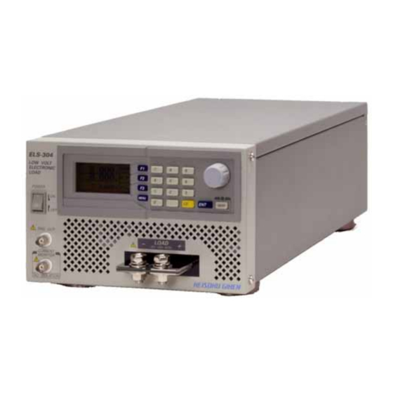
- Page 1 High SPEED Electronic Load SERIES ELS-304 OPERATION MANUAL Engineering Company...
- Page 2 This manual should be kept in a place accessible easily. Please attach this manual to this product when you relocate them. This manual is written based on the functions of this product when shipped from KG. The specifications are subject to change without any notice.
- Page 3 ELS-304 For your safe use of this Product This section describes the Handling Instructions when you use this Product in safety. You are requested to understand and follow these instructions without fail. It is not our responsibility for any accidents caused by the ignorance of the instructions or improper handling or operation.
-
Page 4: Input Power
ELS-304 Input Power Do not input the Volt. other than specified for this product. (The input rated for this product is AC100V-240V 50/60Hz) And Do not used the AC Power Cable that is attached to this product.(Rated of the attached Power Cable in Japan is AC100V)Use the proper cable that meets the Volt. -
Page 5: Maintenance
ELS-304 Move Before you move this product, turn off the power , and remove all the cables from this product. When you move this product , attach this manual to the product, and use the dedicated or more robust packing material. ... -
Page 6: Safety Symbols Used In This Manual
ELS-304 Safety Symbols used in this Manual To used this Product correctly and safely, the following symbols are used in this Manual and this Product. Please review the following to understand the meaning of each symbol and us this Product with cake about the safety. This is a symbol label used both in this manual and on this ... - Page 7 ELS-304 Preface Index of this Manual This Manual describes the following contents. Chapter 1. Outline The Outline and the Functions of this Product is described. Chapter 2. Connections The Connections and the Cautions when you connect are described. Chapter 3.
- Page 8 ELS-304 Check Items when you unpack When you unpack this Product, please check if there are any heavy damage on the package during the Transportation and if there is any missing attachments. If there are any missing attachments, please contact dealer or us promptly. The attachments of this Product are as follows.
- Page 9 ELS-304 Cautions when you move this Product When you move this Product, take the grip to carry this Product. CAUTION ・ When you move this Product, please turn off the Power of this Product in advance. Take this Grip to carry this Product. CAUTION ・ ...
- Page 10 INDEX For your safe use of this Product Ⅰ Safety Symbols Ⅳ Preface ------------------------------------ Index of this Manual ------ Check Items when you unpack------- 2 Cautions when you move--------------- 3 1. Outline ---------------------------------------------------------------------------------- 1.1 Outline 1.2 Features 1.3 Applications 1.4 Options 2. ...
- Page 11 6. Operations for Meas. modes ---------------------------------------------------------- 6-1 6.1 Meas. Value Display 6.2 Sampling Rate 6.3 Volt. / Curr. Ranges 7. Alarms -------------------------------------------------------------------------------- 7.1 Over Current Limit 7.2 Over Voltage Alarm 7.3 Overheat Alarm 7.4 Reverse Connection Alarm 7.5 Over Power Alarm 7.6 Release an Alarm ...
- Page 12 ELS-304...
- Page 13 ELS-304 1. Outline 1.1 Outline This product, ELS-304, has realized as fast as 200A/usec fast load response speed, slew rate that any other products have never realized so far due to our unique new type of load circuit. Ideal noiseless rising and falling waveforms that could not be achieved by any prior art such as simple semiconductor switches have been realized in this ELS-304.
- Page 14 The ripple noise converter is a factory option and you cannot purchase this RC-02A alone and add this option by yourself. With this option, Measurement of the ripple noise can be controlled via GPIB and USB. Contact a dealer you purchased from or KG directly for any questions. 1-2 Product outline ...
-
Page 15: Power Cable
ELS-304 2. Connections This chapter describes some instructions about the connections to pull the full potential of this product. 2.1 Power Cable For a customer in Japan, we attach a AC Power Cable for 1φAC100V with 3-prongplug. Please be careful when you connect the cable because you may get an electric shock. WARNING ・ ... -
Page 16: Load Terminal
ELS-304 2.2 Load Terminal TARGET DEVICE (1) Remote Sense Cable Never fail to connect a Remote Sense Cable that should be shielded or twisted. If the Remote Sense cable is NOT used, Volt Meas. at the Load Terminal and Data in each Load Modes (CR, CV, CP) using the Volt, Reference may have errors. - Page 17 ELS-304 (2) Load Cable As shown in the Fig2-2-1, please use hexagon nuts and hexagon head bolts when you connect load cables. Also please use load cables adapted for necessary current capacity and wire the load cables as short as possible. In addition, twist the load cables if the cable length is long and/or if possible.
- Page 18 ELS-304 WARNING ・ In case of reverse connection, this product alarms due to internal short condition. But this product may be damaged if the current caused by the short exceeds max. rated curr. (120A). ・ When you connect to a target device, never fail to power OFF the target device. ・ ...
- Page 19 ELS-304 2.3 CURRENT MONITER This CURRENT MONITER can be used when you observe a current waveform by an oscilloscope. NOTE ・ The CURRENT MONITER of this unit is NOT isolated. Please be careful when you connect to an oscilloscope. Improper connections would cause damage. ・ ...
- Page 20 ELS-304 NOTE ・Connection to an oscilloscope. When you connect this product to an oscilloscope, please be careful about the polarities of the probes of the oscilloscope to connect as shown in the Fig. 2-3-1. ELS-304 Oscilloscope Load Circuit Probe Load Terminal Moniter...
- Page 21 ELS-304 2.4 TRIG OUT TRIG OUT signal can be used when you observe a waveform in dynamic mode operation. NOTE ・ TRIG OUT of this product is an isolated output. ・ Trigger signal is outputted only when dynamic mode operation. ・ ...
- Page 22 ELS-304 2-8 Connections ...
-
Page 23: Name And Function Of Each Part
ELS-304 3. Name and Function of Each Part Name and the functions of each part are described. 3.1 Front Panel (1) Display A 128x64 dot monochrome LCD panel. It displays setting and meas. values etc. (2) Operation Panel This panel consists of function keys, a rotary knob to change values, and ten keys to input values. - Page 24 ELS-304 (6) Trigger Output In dynamic (load) mode, sync. Signals in accordance with the edges of the load current will be outputted. This signal is isolated. (7) Power switch Switch for powering ON/OFF of this product. 3.1.1 1 Details of the Display (1) Volt.
-
Page 25: Rear Panel
ELS-304 (7) Load modes Abbreviation of currently selected load mode is displayed. Abbreviation represent as follows. constant current mode constant resister mode constant voltage mode constant power mode ext. control mode short mode (shorted) (8) Icon indicating the scale of increase/decrease load setting by the rotary knob Unless you operate in some specific items, you can use the rotary knob to change load setting. -
Page 26: Side Panel
ELS-304 (2) GP-IB Connector This connector conforms to IEEE488.1. You can control this product from a general GP-IB Controller. (3) USB Connector This is a connector to connect a personal computer. Conforming to the USB1.1 Standards, this product can be controlled from a personal computer easily via USB by Using the attached device driver and control library. -
Page 27: Operation Panel
ELS-304 4. Operations Names and functions of the operation panel, menu selection, memory function, and configuration setting are described. 4.1 Operation Panel MENU ON/OFF Function keys These function keys are used to recall function allocated for each menu selected. (2) Ten keys These keys are for setting values like load current. -
Page 28: Menu Selection
ELS-304 4.2 Menu Selection There are three (3) menus available in this product. ・LOAD CONTROL you can setup about load. ・MEASURE SETUP you can setup about measurement. ・I/O – MEMORY you can setup GP-IB address and I/O. First of all, it is necessary to select proper menu mode. To select proper menu, press “MENU”... - Page 29 ELS-304 4.3 I/O Setting I/O setting consists of the following settings. ・GP-IB address ・Contrast of the display (LCD) ・Brightness of back light of the display (LCD) (1) GP-IB address First, call the “I/O – MEMORY” by the method as described above 4.2. Press “F1”...
-
Page 30: Memory Function
ELS-304 4.4 Memory Function You can save up to six (6) groups of setting conditions, and recall any of those conditions freely. Parameters that you can save in this memory function are as follows: ・currently selected load mode ・Load setting value(s) in each load mode ・Load response speed (slew rate) in each load mode ・Current Limit value ・Parameters for dynamic load operation... -
Page 31: Load Mode
ELS-304 5. Operations for Load Modes There are seven (7) Load modes in this Product. There are the Constant Curr. (CC) , Constant Resistor (CR), Constant Volt. (CV), Constant Power (CP), External Control (EXT), Dynamic Load (DYNAMIC) ,and Short (SHORT) modes. Please check which Load mode you use and follow the operations relevant to the mode according to this manual. - Page 32 ELS-304 CC MODE CR MODE SHORT CV MODE MODE CP MODE EXT MODE Fig.5-1-1 Menu of Each Load Mode (Loop Structure) Turn the knob until the load mode you want to select. Press “ENT” key or the knob to switch to the load mode. Or before you switch to the load mode, you can setup values of the load mode.
- Page 33 ELS-304 (1) Ten keys You can input values directly by using the “ten keys”. The values you can input are those in the load mode currently displayed. You can inputting/changing values regardless of Load ON/OFF. Use “ten keys” to input values and press “ENT” key to confirm it. Example: setup 98.50A in CC mode Note:...
-
Page 34: Response Speed
ELS-304 5.3 Response Speed You can change the response speed (slew rate) of both rising and falling time that are effective when load is ON/OFF and load condition changes. The response speed depends on the current range selected then. The max response speed are 200A/μsec at 120A range and 20A/μsec at 12A range. - Page 35 ELS-304 5.5 Constant Curr. (CC) Mode In this CC mode, Constant Current flows regardless of the Load Volt. Setup Current Load Cuurent Input Volt. (1) Press the “rotary knob” to set mode select condition. and then turn the knob until “CC” is displayed as shown below.
- Page 36 ELS-304 5.6 Constant Resistor (CR) Mode In the CR mode, the load will act as like a constant resistor because the Current proportional to the Load Volt flows regardless of the Load Volt. This is the best Load mode in some general Load Testing.
- Page 37 ELS-304 5.7 Constant Volt. (CV) Mode For power supplies having internal resistor, the Load current will change so that the Load Volt. This mode is optimal for rechargeable batteries Testing. Load Setup Voltage Cuurent Input Volt. Press the “rotary knob” to set mode select condition. and then turn the knob until “CV” is displayed as shown below.
- Page 38 ELS-304 5.7.1 CV+Climit Mode In this CV +Climit mode ,by using the curr. limit function in the configuration setting, you can limit the load current in CV mode. Cuurent-Limit This is adapted for simulating the charge characteristics of batteries. You can set the current in about 110% of the value you set in curr.
-
Page 39: Constant Power (Cp) Mode
ELS-304 5.8 Constant Power (CP) Mode In this CP mode, the Load Current changes so that the Load Power should be constant. This mode can simulate devices like switching power supplies whose current increases as the Volt. decreases. Setup Power Load Cuurent Input Volt. - Page 40 ELS-304 5.9 External Control (EXT) Mode In this External Control (EXT) Mode, the Load Current proportional to the External Volt. will flow. Load Cuurent Extrnal Control Setting Current Extrnal Control Volt. Press the “rotary knob” to set mode select condition. and then turn the knob until “EX” is displayed as shown below.
- Page 41 ELS-304 5.10 Short (SHORT) Mode In this mode, load terminals are shortened Load current can flow up to the rated 120A or setup current limit whichever smaller, but the current range is fixed to 120A . Press the “rotary knob” to set mode select condition. and then turn the knob until “ST” is displayed as shown below.
- Page 42 ELS-304 5.11 Dynamic (DYNAMIC) Mode In this mode, load current changes alternately between two setup values according to the period of each load value. This mode can be used along with CC, CV, CR, CP, EXT, or SHORT mode. Load Cuurent Setting Period...
- Page 43 ELS-304 (2) Load mode Load mode selected is kept effective when you setup dynamic mode. For example, if CC mode is selected, then you select dynamic mode, the CC mode is still effective. But if you change the load mode while dynamic mode is select, the dynamic mode is stopped and the selected mode is selected.
- Page 44 ELS-304 (5) Setting parameters. The following figures illustrate the difference of auto and single operation in dynamic mode. Current (A) Current (A) N o te ; T IME(CC2) = 0.00mS TIME(CC1) TIME(CC2) TIME(CC1) SET(CC1) SET(CC1) SET(CC2) SET(CC2) RESP(CC2) RESP(CC1) RESP(CC1) (A/usec) (A/usec) (A/usec)
- Page 45 ELS-304 (6) Execute After you setup values for both “CC1” and “CC2”, you can start operation. To start dynamic operation, in the dynamic load setting menu, press “F3” to display ON/OFF window. Then press “F3” or turn the “rotary knob” so that the ON is underscored. And press “ENT”...
- Page 46 ELS-304 Ex. 2 SINGLE For Single operation setting, set effective time of CC2 for zero (0). Then the single pulse of CC1 is output as shown in Fig.5-11-6. Note: If you set the effective time of “CC1” for zero (0) instead, this single operation won’t be executed.
- Page 47 ELS-304 6. Operations for Meas. Modes This product has three (3) Measurement Modes for Curr. Volt. and Power Meas. There are two (2) Ranges, i.e. High and Low Ranges, for Curr. and Volt. Measurements, enabling a user to measure accurately. For ripple noise measurement, there is an optional RC-02 meas.
-
Page 48: Sampling Rate
ELS-304 6.2 Sampling Rate To cancel the influence of ham noise, you can select sample frequency of A/D converter in this product. Usually you select the same frequency as the commercial line. (1) Select frequency To select sample frequency, display MEASURE SETUP menu. Press “F3”... - Page 49 ELS-304 (2) Current range setting Press the rotary knob three times quickly. Once Twice Three times After you press the knob once, MODE is displayed in the dot circle in the upper figure. When you press the knob three times quickly, “Cr” is displayed. Turn the knob to select “12A”, “120A”, or “AT”...
- Page 50 ELS-304 6-4 Operations for Meas. Modes...
- Page 51 ELS-304 7. Alarms The protection functions and alarms of this product are described. When an Alarm occurs, beep sound rings, an error message is displayed, and the Load will promptly be set OFF to the no-load condition. 7.1 Over Current Limit When this alarm works, the Load Current is limited to protect the Load section of this product.
-
Page 52: Overheat Alarm
ELS-304 7.3 Overheat Alarm This alarm works when the temperature at a heatsink section in the load section exceeds 80-Celsius degrees. Fig.7-3-1 Display of Overheat Alarm CAUTION ・ This alarm may work if you put an obstacle near the air inlet or outlet of this product, or the fan of this product is not working due to dusts or something else, or if this product is used beyond the operating temperature range of this product. - Page 53 ELS-304 7.4 Reverse Connection Alarm This alarm works when Iin≦-1.5A (120A Range),Iin≦-1.0A (12A Range) Where: “Iin” is the load current. Fig.7-4-1 Display of Reverse Connection Alarm WARNING ・ This is for the alarm only, there is no protection for the Load Section of this product.
- Page 54 ELS-304 7.5 Over Power Alarm This alarm works when 315W ≦Pin. Fig.7-5-1 Display of Over Power Alarm 7.6 Release an Alarm Press “CE” key to release the alarm. Please remove the cause of the alarm as well. MENU ON/OFF Fig.
-
Page 55: Programming Mode
ELS-304 8.Programming Mode This product has the GPIB (compliant to the IEEE488-1) and USB (compliant to the ) interfaces as standards. From the panel operations, some parameters can be setup and the Curr./Volt. readback data can be displayed on the DISPLAY on the front panel, which enable a user to configure an automatic measurement system easily. - Page 56 ELS-304 8.2 Meas. Commands Function Command Description Memo Load curr. meas. MC{NR1} range 0〜2 0:AUTO range readback value:real number(##.###) 1:curr.High range 2:curr.Low range Volt. at the load MV{NR1} range: 0〜2 teminal meas. 0:AUTO range readback value:real number(##.###) 1:volt.High range 2:volt.Low range Power meas. Load terminal volt.×load curr. calsulated power result is back readback value:real number(##.###) Define meas. display DS{NR1} range: 0〜1 Display where upper or lower are 0:define upper Meas.display effective is define when GPIB 1:define lower Meas.display measured Mes. Fixed mode MF{NR1} range 0〜1 meas. command selected last will be 0:free run meas.
-
Page 57: System Commands
ELS-304 8.3 Load Setting Commands Function Command Description Memo Load Setting CC{NR2} Constant Curr.〔A〕 CR{NR2} Constant Resistor〔Ω〕 CV{NR2} Constant Volt.〔V〕 Both mode and setting value can be CP{NR2} Constant Power 〔W〕 Curr.value when ext.cont.volt is 10V setup. CX{NR2} 〔A〕 Short Curr. range is set as HIGH range This command is to select the range: 0〜1 Dynamic operation mode only. CD{NR1} 0:stop/shift dynamic operation Detailed Setting shall be done by 1: start dynamic operation other commands below Dynamic DP{NR1} range: 0〜1 Section where DC DT and DR 1:define section "CC-1" commands are effective is defined 2:define section "CC-2"... -
Page 58: Status Register
ELS-304 8.5 Multi Line Messages The multiline message is effective when ATT signal is "Low". The following functions are supported in this unit. Function Code Description Memo Device clear DCL (Device Clear) becomes the same condition as power 4 SDC (Selected Device Clear) Trigger 8 GET (Group Execute Trigger) repeat the lastly issued command Panel Operations 1 GTL (Go To Local) release remote condition LLO (Local Lock Out) prevent from releasing remote condition... - Page 59 ELS-304 8.7 GPIB Sample Programs Sample programs of Visual Basic using a GPIB card / board of National Instruments are presented. For detailed explanation about the driver of the GP-IB card / board , and Visual Basic etc, please refer to relevant documents. The part of Private Sub InitIF() in the sample program is the function to initialize the GPIB bus used in each sample section.
- Page 60 ELS-304 Option Explicit Dim IFid As Integer ' NI I/F Device ID Private Sub InitIF() If 0 <= ilfind("GPIB0") Then ' Init I/F IFid = ildev(0, 1, 0, T3s, 1, &HC0A) ilsic 0 ' Interface Clear ilsre 0, 1 ' Remote Enable ilwrt IFid, "INI", 3 Sleep 3000 Else...
- Page 61 ELS-304 Private Sub Command2_Click() ' Start of sample -2) Call InitIF ' initialize GPIB I/F ilwrt IFid, "SW1", 3 ' LOAD ON ilwrt IFid, "CC2", 3 ' Set constant curr. 2A ' ① ilwrt IFid, "DP1 DC5 DT10", 12 ' CC-1=5A TIME-A=10msec ilwrt IFid, "DP2 DC3 DT40", 12 ' CC-2=3A TIME-B=40msec...
-
Page 62: Usb Interface
ELS-304 8.8 USB Interface If you have a windows 2000/Xp PC with USB I/F, you can control ELS-304 from VBA like Visual Basic and Excel by installing the driver and using a USB cable. The command system in the USB control is almost equal to that in GPIB control. Environment requirements Microsoft Windows2000 Professional ... - Page 63 ELS-304 (d) Click “Next >”. (e) Select the folder where the software is installed Default setting is C:¥Program Files¥KEISOKU GIKEN ELSeries After you select the folder, click “Next >”. (f) Check the install Programming Mode 8-9...
- Page 64 ELS-304 This is the final check. If there is no problem, click “Next >”. (g) End of installation This is the end of installation display if there is no problem. ※ For your uninstall, you can do it by Windows “Application addition and Delete” 8-10 Programming Mode ...
- Page 65 ELS-304 Install the Device Driver This is the explanation of the installation of USB device driver. Never fail to put the SUPPORT CD for EL Series Electronic Load CD-ROM in the PC. (a) Connection of ELS-304 Connect between the PC and ELS-304 with a USB cable. (b) A message “a new hardware was found”...
- Page 66 ELS-304 (e) Search menu of the driver file is then displayed. Select, “”select the place” and click “next” or「次へ(N) 」. (f) Designate the place where the “el.Inf” file is . The “Inf” file is located in the folder where you installed by the “SUPPORT CD for EL Series Electronic Load CD-ROM”...
- Page 67 ELS-304 (g) After the search ends, click “next” or「次へ(N) 」 to start the installation. (h) End of the installation. If there is no problem, the menu below is displayed and this it the end. Programming Mode 8-13...
- Page 68 ELS-304 8.9 ActiveX Control Functions Reference NOTE ・ Do not use any commands other than blow which may be included in the library. Those commands are for maintenance use only by our authorized engineers, and use of those commands would cause changing the setting which is out of the specifications.
- Page 69 ELS-304 ・MeasureSample(times As Integer) As long Select the number of averaging times 0:1 time, 1:3 times, 2: 5 times. ・LoadON Set Load ON ・LoadOFF Set Load OFF ・ResetAlm Reset the alarm ・Version Acquire ROM version information. Programming Mode 8-15...
- Page 70 ELS-304 8.10 Usage of Active X from Excel The method of selecting the Active X by Excel’s Visual Basic is explained. (1) Start-up the Excel, and select “Display ”> “Tool bar (T) ”-> “Control Toll Box” Select (2) Select “KEISOKU GIKEN EL Series Control” (3) Drug on the worksheet and the following mark is come up.
- Page 71 ELS-304 8.11 USB Sample Program A program sample using the Excel’s Visual Basic is explained. For Visual Basic, refer to the relevant document etc. . Sample program Read the firmware version of ELS-304 and display it on a worksheet. Fig8-11-1 ...
- Page 72 ELS-304 8-18 Programming Mode ...
-
Page 73: Specifications
ELS-304 9. Specifications The specifications are base on the following conditions unless otherwise described. * Warm up time for 30 minutes or more * Temp. :23℃±5℃, Humid 70% or less 9.1 General Gneral Fonnt panel input Load Terminal Power AC100〜240V 50/60Hz Consumption Power 40VA or less (when AC100V) - Page 74 ELS-304 9.3 Load Section Max. rated 120A Curr. Volt. 300W Power Constant current setting Curr. Range 120A Nominal Resolution *1 10mA ±0.2% of stg. ±0.2% of fs. Accuracy Load Resonse *4 0.2A/µsec〜20A/µsec 2A/µsec〜200A/µsec 100nS Min. Load Resp. Time *3 Constant resistor setting (4V range) Curr.
-
Page 75: Output Section
ELS-304 9.4 Output Section TRIG OUT Pulse trans output Output *1 50Ω Output Impedance 4usec (typ) Output Pulse Width +/-3V(typ) Output max. peak volt CURRENT MONITER 10V/120A fs. Output *2 50Ω Output Impedance ±1% of Conv.Volt. ±1% of fs. Accuracy *3 *1 "TRIG OUT"... - Page 76 ELS-304 9-4 Specifications ...
-
Page 77: Maintenance/Calibration
ELS-304 10. Maintenance/Calibration Executing the pre-scheduled Maintenance and Calibration would be highly suggested for long use. 10.1 Cleaning To clean this product, use a soft or wet cloth. CAUTION Before you clean this product, power this product off and disconnect the power plug. ・ ... - Page 78 ELS-304 As shown below, remove the power Fuse, and then exchange the Fuse. 1.Remove the Power Fuse Use a Minus Driver to pull out the Fuse. 2.Exchange the Power Fuse Power Fuse Preliminary Fuse Exchange the Power Fuse by the preliminary Fuse located next to the Power Fuse in use. If there is no preliminary Fuse there, use a Fuse with the same spec suitable for the necessary standards.
- Page 79 High Speed Electronic Load Series ELS-304 OPERATION MANUAL M-2099-02 Rev1.2 Issue Date August 19 2005 KEISOKU GIKENCO.,LTD. 2-12-2, Chigasaki-minami, Tsuzuki-ku, Yokohama 224-0037 JAPAN http://www.keisoku.co.jp/ Contact Us For sales TEL: 045-948-0211 FAX: 045-948-0221 E-mail: PWsales@hq.keisoku.co.jp For Engineering TEL: 045-948-0214 FAX: 045-948-0224 E-mail: PW-support@hq.keisoku.co.jp...
Need help?
Do you have a question about the High Speed Electronic Load Series and is the answer not in the manual?
Questions and answers