Table of Contents
Advertisement
Quick Links
Advertisement
Table of Contents

Summary of Contents for Lesco SUPERSPOT VSM3002
- Page 1 MAX / MAX HP Model: VSM3002 UV SPOTCURE SYSTEM 100 / 200 WATT TECHNICAL REFERENCE MANUAL This product conforms to CE Standards See Appendix B for details AUV\LESCO A DIVISION OF AMERICAN ULTRAVIOLET COMPANY WWW.LESCOUV.COM 23555 Telo Avenue REV. Torrance, CA 90505 3/21/2012...
- Page 2 KMD1042H...
- Page 3 KMD1042H...
- Page 4 KMD1042H...
- Page 5 WARRANTY POLICY WARRANTY: Fiber optic lightguides sold by AUV\LESCO are warranted to be free from defects in material and workmanship under normal and proper use for 60 days from date of original shipment. This warranty applies solely to defects in material and workmanship. AUV\LESCO will repair or replace at its option, any defective fiber optic lightguides when returned to AUV\LESCO by the purchaser, all transportation paid by the purchaser, within 60 days from date of original shipment.
-
Page 6: Table Of Contents
Table of Contents General Information ................... 7 1.1 Scope of Manual ..................7 1.2 System Description ................... 8 Safety ......................... 9 2.1 Ultraviolet Radiation .................. 9 2.2 Power up ....................10 Component Descriptions .................. 11 3.1 Front Panel ..................... 11 3.2 Back Panel.................... - Page 7 8.2 Optical Components ................32 Drawings/Schematics ..................36 9.1 Main Schematic ..................36 9.2 I/O Connector - Parallel Interface ............43 9.3 Serial Communication ................45 10.0 Accessories ...................... 48 10.1 Standard Replacement Parts ..............48 10.2 Optional Liquid-Filled Lightguides ............48 10.3 Fiber Optic Lightguides ................
-
Page 8: General Information
1.1 Scope of Manual This manual provides information necessary for operating and maintaining the AUV\LESCO SUPERSPOT MAX UV spot curing system (the MAX). It also includes safety requirements and references to pertinent mechanical and electrical drawings. Throughout this manual, precautions necessary to prevent injury to personnel are preceded by the heading WARNING;... -
Page 9: System Description
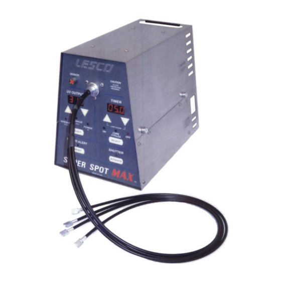
1.2 System Description The AUV\LESCO SUPERSPOT MAX curing systems are ultraviolet (UV) light sources that provide an intense concentration of UV light for the purpose of spot curing UV sensitive materials (photo polymerization). The MAX is the most powerful UV spot curing system that utilizes a lightguide delivery method (liquid filled or fiber type). -
Page 10: Safety
• Special rubber feet designed for use in clean rooms Safety The AUV\LESCO UV spotcure system has been designed to operate safely. They are being used in a wide variety of industrial environments worldwide without any worker safety problems or health hazards. However, this equipment can present worker safety problems if care is not taken to install and operate correctly. -
Page 11: Power Up
allowing any skin surface from coming within close proximity of the high intensity light output(s). Additionally, it is never advisable to stare directly at any high intensity light source whether visible or ultraviolet for prolonged periods unless precautions have been taken to reduce both visible and ultraviolet light to safe levels. -
Page 12: Component Descriptions
Component Descriptions 3.1 Front Panel The front panel is a membrane control pad with digital displays and LED indicators. The keypad controls all the major operating features of the MAX. Distal UV sensor Lightguide Port/Receptacle Connector UV digital display Timer digital display ON time Number of cure Power to the bulb in watts... - Page 13 The electric power displayed is the necessary excitation applied to the bulb to achieve the required intensity. It is a useful indicator to monitor the status of the bulb or its performance. The SELECT button is used to change modes. Each time the SELECT button is pressed, a different LED illuminates the specified mode.
-
Page 14: Back Panel
3.2 Back Panel The MAX housing is made of stainless steel, making it ideal for clean room applications. The following parts and connections are located on the rear of the system. Cooling Fan I/O Connector Footswitch Connector Power Control Switch RS-232 Connector RS-485 Connector ** CAUTION **... - Page 15 3.2.2 Power Entry Module It contains the power switch, power cord socket (IEC type), main fuse, and EMI filter. ** WARNING ** For continued protection against risk of fire, replace only with the same type and rating of fuse. Input volts Fuse rating 115-120 4A T, 250 VAC, Slow Blow...
-
Page 16: Housing
3.3 Housing The MAX housing is made of stainless steel, making the equipment suitable for clean room operations and allowing for easy cleaning. The housing consists of 3 main sections: Chassis - The vertical design allows for more efficient use of counter-top space. The optical assembly is located in the upper compartment. - Page 17 3.3.1 Lamp Housing Compartment This area contains the optical transmission assembly, bulb, reflector, optical feedback sensor and electrical lamp connections. The function and relationship of each component in the lamp housing is described below: Bulb Reflector Sub-Assembly Light guide Receptacle UV Bulb UV Bulb Connector Block 3.3.2 Shutter Assembly...
- Page 18 3.3.3 Bulb The MAX uses a proprietary high-pressure short arc mercury vapor bulb designed for long life at very high intensity. 3.3.4 Reflector The reflector is a high precision, first surface elliptical reflector used to gather and focus the highest concentration of the available energy from the bulb. 3.3.5 Bulb Reflector Sub-Assembly The Bulb Reflector Sub-Assembly is detachable, and it consists of the bulb holder and an elliptical metal-formed reflector.
-
Page 19: Special Features
3.3.8 Light guide Receptacle The Lightguide Receptacle is a precision mechanical assembly that aligns the bulb, bulb reflector assembly, and lightguide for optimal focal point location. It also supports the shutter assembly, optical feedback sensor, lightguide safety switch, and infrared filter. 3.4 Special Features Here are several special features that can be accessed via the front panel. -
Page 20: Interior Control Components
3.4.3 Alarm Latching The High Limit Alarm indicator can be latched on. If an alarm is latched on, it will remain set on until power is turned off. The Alarm Reset button will silence the beeper sound only. When the non-latching mode is selected, the Alarm indication (both visual and audible) will extinguish upon shutter closure. - Page 21 The Display/CPU board allows setting of the UV output; shutter ON/OFF times and number of desired exposures, power alert and reset, hour meter and provides access to user calibration procedure. All these functions are explained in Section 3.0. The CPU on this board and the battery back up SRAM allow data storage for up to 5 years, which is accessible through the serial communications ports located on the rear panel (see Section 3.2).
-
Page 22: Installation/Start Up
Should one find any major damage immediately inform the shipping company and AUV\LESCO. Note: Any delay in reporting damage may invalidate the claim. Make sure to keep the shipping container in case there is a need to ship the system or components back to AUV\LESCO. - Page 23 4. Replace the nut on the end of the bulb and tighten against the reflector base. Then, using serrated pliers tighten the nut 1/8 to 1/4 turns. UV Bulb Knurled nut Reflector Bulb Connector Reflector base Bulb ** CAUTION ** Lamp surface is hot during normal operation.
-
Page 24: Voltage Setting
Safety glasses are provided with each system. Avoid exposing skin to UV light. Shielded UV enclosures and safety glasses are available for purchase from AUV\LESCO. ** CAUTION ** Check input voltage and set input power module switch before plug in. - Page 25 See Detail A-A Figure 1. Detail A-A To change from 120VAC to 240VAC input, move the connector shown in Detail A-A 1 pin position forward as shown below. Voltage Selection Connector 120 VAC 240 VAC Figure 1A. Voltage Setting. KMD1042H...
-
Page 26: Operation
Operation Turn on the power switch located on the back of the MAX above the power cord receptacle. After an initial hardware check, indicated by the sequential illumination of the front panel indicators, the system shows its serial address in the front displays as Adr XX and then ignites the bulb. -
Page 27: Alarm Latching (Al)
5.2. Alarm Latching (Al) The Optical Feedback Alarm is set when the control loop can no longer operate. When the Alarm Latching mode is selected, the indicator will remain ON until power is turned off, including the ALARM LED blinking, the I/O connector output and the serial interface. The buzzer will also sound, but it may be silenced by pressing the ALARM RESET button. -
Page 28: Calibration Error
Once the Low value is found, that number will freeze in the left-hand display and the right-hand display will continue the count until the high value is found. The high value corresponds to the highest bulb output at the power supply maximum setting. Once these values are found, the shutter will close automatically. -
Page 29: Serial Communication Datamax
Please note the individual address of the MAX unit displayed during power up before lamp ignition. Please refer to the Serial Interface Document, AUV\LESCO Part No. KMD1043, that details all the available commands and their functionality and programming. The lists of... -
Page 30: Data Max Interface
There is a Virtual Instrument (VI) interface to help communication to the MAX unit using a standard computer or a laptop. The available kit includes the software and cables required to connect the computer to the unit. Please see AUV\LESCO Document KRM1011 for DataMAX Software Instructions and detailed description of the kit components. -
Page 31: Maintenance
Maintenance 8.1 Housing The MAX is a simple, rugged unit and does not require complicated routine maintenance. Routine maintenance consists of keeping the unit clean, periodical cleaning of air filters, and periodical UV output measurements to ensure that the unit performs optimally. 8.1.1 Cleaning **WARNING** Make sure the main power switch is turned off and... - Page 32 For 120vac Fuse 4A in first line Jumpered in second line. Spare fuse 4A For 220vac Fuse 2A in first line Remove the jumper Install a 2A fuse in second line Correct fuse placement in holder No fuse Correct Incorrect Contacts Fuse not making contact KMD1042H...
-
Page 33: Optical Components
Always inspect the reflector when replacing bulbs. discoloration or lack of clear shiny surface indicates a worn out reflector. AUV\LESCO recommends replacing the reflector assembly every 6-12 bulb changes or earlier if required. Many factors influence its performance, such as air humidity, room temperature, and potential corrosives/particulates content within the ambient air. - Page 34 INSTRUCTIONS TO REPLACE THE IR FILTER Remove the top cover 2. With a flat screwdriver loose the set screw 3. Remove the filter assembly 4.With a .050” Hex Driver remove the three screws 5. Remove the filter rear holder and IR Filter 6.
- Page 35 8mm or 3mm diameter models. AUV\LESCO also offers a variety of custom light guides for special purposes. These include special models optimized for high transmission in the UV “B” and UV “C” range (230 to 390 nm). Contact AUV\LESCO for price and delivery of special products.
- Page 36 5. If the fiber surfaces cannot be cleaned or continue to release material, please return the FOLG to AUV\LESCO for repair. It may be necessary to re-polish the surfaces or rebuild the ends. 6. Always inspect the IR filter in the Super Spot unit, since it is essential for the protection of the proximal (entrance) end of the FOLG.
-
Page 37: Drawings/Schematics
Drawings/Schematics The following section is a set of drawings and schematics complete with specifications for the MAX system and accessories. 9.1 Main Schematic KTM2224 Electrical Schematic KMD1042H... - Page 38 KMD1042H...
- Page 39 KMD1042H...
- Page 40 KMD1042H...
- Page 41 KMD1042H...
- Page 42 KMD1042H...
- Page 43 KMD1042H...
-
Page 44: I/O Connector - Parallel Interface
9.2 I/O Connector - Parallel Interface The MAX unit incorporates an external parallel interface connector in its back panel. The MAX unit communicates with external equipment using inputs and outputs. There are several combinations available that include different shutter trigger signals and external safety interlock. - Page 45 I/O Pin-Out viewed from rear of unit 9.2.1 Standard Parallel Interface Input Option 9.2.1.1 VUM1029 A jumper between pin 1 and pin 2 will activate the shutter cycle. If a semiconductor switch is used, the sourcing input pin 1 must be drain to pin 2 with a device able to handle 15mA DC.
-
Page 46: Serial Communication
RS-485 Up to 4000 feet on Category 5 solid cable RS-232 Up to 25 feet AUV\LESCO can provide RS485 adapters, cables and remote software to communicate serially with up to 100 MAX units from a single cable drop. See Section 7.2. - Page 47 9.3.4 Connection Cable RS485 DB 9 DB 9 Inverting Receiver Input Non-Inverting Receiver Input RS485 Adapter MAX 00 MAX 01 MAX 99 9.3.5 Connection Cable RS232 DB 9 IMPORTANT NOTICE: RS232 for point-to-point (1 unit) application, NOT intended for Multidrop Network. Computer RS232 KMD1042H...
- Page 48 9.3.6 Networking Adapter SSM3076 for VSM3002 Use Adapter SSM3076 for Super Spot MAX Model VSM3002 networking. SSM3076 adapts the RS-485 DB9 standard connector (VSM3002) to the RS-485 circular connector (VSM3001). KMD1042H...
-
Page 49: Accessories
10.0 Accessories 10.1 Standard Replacement Parts To order replacement parts please call the AUV\LESCO spare parts dept. in Torrance, CA. TOLL FREE (800) 615-3726 or (310) 784-2930. Shutter NZB1010 2 Amp, 120V AC input fuse EFB1008 4 Amp, 240V AC input fuse... -
Page 50: Recommended Spare Parts Kit
10.4 Recommended Spare Parts Kit RECOMMENDED SPARE PARTS KIT FOR VSM3002 SSMAX100W (Level I – qty 1-4 units)______________ .LESCO Part # Description EFB1007 Fuse, 4 Amp, 250V EFB1008 Fuse, 2 Amp, 220V EPB1054 Top & Bottom fan ITB1096 Teflon stop... - Page 51 RECOMMENDED SPARE PARTS KIT FOR VSM3002 SSMAX 200W ____________________ (Level I – qty 1 – 5 units)_____________ .LESCO Part # Description EFB1007 Fuse, 4 Amp, 250V EFB1008 Fuse, 2 Amp, 220V EPB1025 Top & Bottom fan ECB2051 Lamp Connector ITB1096...
-
Page 52: Troubleshooting
11.0 Troubleshooting *** CAUTION *** PARTS MAY BE HOT. If unit was running allow time for cool down. Exercise care when touching internal optical parts. *** WARNING: HIGH VOLTAGE *** High voltage may be present in bulb terminal connections. Allow 2 minutes to bleed down capacitor voltage. *** CAUTION *** Disconnect power from system or unplug system from wall or VAC power source before connecting the footswitch adapter. - Page 53 Open circuit voltage (no bulb). Open circuit voltage should rise to approx. +2340 Vdc for a few seconds, and then drop to approx. +330 Vdc. If power supply blows fuses without a load, then power supply components, wiring or shorts may be the problem. Perform visual inspection of power supply components and wiring.
- Page 54 IR filter) are intact and functioning correctly by taking radiometer reading with calibrated radiometer and AUV\LESCO Quartz Test Fixture. Verify that the lightguide is properly pushed completely into the lightguide socket (and that the ball plunger is in the detent groove if applicable).
- Page 55 (see Lightguides section of this manual or AUV\LESCO website). **WARNING** Bulbs are extremely hot when first shut off and can cause severe burns! Disconnect and remove the bulb; inspect the bulb visually. (NOTE: Do not touch quartz surfaces, particularly if hot.
- Page 56 Appendix A – UV Protective Eye Glasses Appendix B – Agency Approvals KMD1042H...
- Page 57 KMD1042H...
- Page 58 KMD1042H...
- Page 59 KMD1042H...
- Page 60 KMD1042H...
- Page 61 KMD1042H...
- Page 62 Appendix C – IR Filter Description Presented here are the different spectral output graphs of our various filters on the UV SpotCure series. Filter OFB1004 280nm-480nm Intensity (counts) 4000 3000 2000 1000 Wavelength (nm) Filter OFB1008 280nm-400nm Intensity (counts) 4000 3000 2000 1000...
- Page 63 Filter OFB1013 275nm-500nm Intensity (counts) 4000 3000 2000 1000 Wavelength (nm) Filter OFB1014 280nm-320nm Intensity (counts) 4000 3000 2000 1000 Wavelength (nm) Filter OFB1019 400nm-500nm KMD1042H...
- Page 64 Filter OFB1021 320nm-420nm Intensity (counts) 4000 3000 2000 1000 Wavelength (nm) KMD1042H...
- Page 65 FOR: SPARE PARTS, SALES, OR SERVICE CALL: ™ AUV/LESCO A DIVISION OF AMERICAN ULTRAVIOLET COMPANY 23555 TELO AVENUE TORRANCE, CA 90505 PHONE: (310) 784-2930 / (800) 615-3726 FAX: (310) 784-2929 / (800) 905-3726 E-mail: Sales@lescouv.com KMD1042H...
Need help?
Do you have a question about the SUPERSPOT VSM3002 and is the answer not in the manual?
Questions and answers