Table of Contents
Advertisement
Quick Links
BX2000
TABLE OF CONTENTS
1.
1.1. PREFACE.......................................................................................................1-1
1.2. KEY FEATHERS ............................................................................................1-1
1.3. PERFORMANCE LIST...................................................................................1-2
1.4. BLOCK DIAGRAM..........................................................................................1-3
1.5. INTRODUCE THE PENTIUM ® II / III PROCESSORS .................................1-4
1.6. WHAT IS AGP? ..............................................................................................1-5
2.
2.1. HARDWARE ..................................................................................................2-1
2.2. SOFTWARE...................................................................................................2-2
2.3. ENVIRONMENT.............................................................................................2-2
3.
3.1. UNPACKING ..................................................................................................3-1
3.2. MAINBOARD LAYOUT ..................................................................................3-2
3.3. QUICK REFERENCE FOR JUMPERS & CONNECTORS...........................3-2
3.4. DRAM INSTALLATION ..................................................................................3-6
3.5. CPU SPEED SETUP......................................................................................3-6
3.6. CMOS RTC & ISA CFG CMOS SRAM..........................................................3-7
3.7. SPEAKER CONNECTOR INSTALLATION...................................................3-8
3.8. HARDWARE RESET SWITCH CONNECTOR INSTALLATION .................3-8
3.9. POWER LED CONNECTOR INSTALLATION..............................................3-8
3.10. IDE & ATAPI DEVICE INSTALLATION .......................................................3-8
1
Advertisement
Table of Contents

Related Manuals for G.B.T GA-BX2000

Summary of Contents for G.B.T GA-BX2000
-
Page 1: Table Of Contents
BX2000 TABLE OF CONTENTS INTRODUCTION 1.1. PREFACE.......................1-1 1.2. KEY FEATHERS ....................1-1 1.3. PERFORMANCE LIST...................1-2 1.4. BLOCK DIAGRAM..................1-3 1.5. INTRODUCE THE PENTIUM ® II / III PROCESSORS .........1-4 1.6. WHAT IS AGP? ....................1-5 SPECIFICATION 2.1. HARDWARE ....................2-1 2.2. SOFTWARE....................2-2 2.3. ENVIRONMENT.....................2-2 HARDWARE INSTALLATION 3.1. - Page 2 Table of Contents 3.11. PERIPHERAL DEVICE INSTALLATION .............3-8 3.12. KEYBOARD & PS/2 MOUSE INSTALLATION..........3-8 BIOS CONFIGURATION 4.1. ENTERING SETUP..................4-1 4.2. CONTROL KEYS ...................4-1 4.3. GETTING HELP .....................4-2 4.3.1. Main Menu ..................4-2 4.3.2. Status Page Setup Menu / Option Page Setup Menu ......4-2 4.4.
-
Page 3: Introduction
BX2000 1. INTRODUCTION 1.1. PREFACE Welcome to use the BX2000 motherboard. It is a Pentium ® II / III / Celeron Processor based PC / AT compatible system with AGP / PCI / ISA Bus, and has been designed to be the fastest PC / AT system. There are some new features allow you to operate the system with just the performance you want. - Page 4 Introduction 30.5 cm x 19 cm ATX SIZE form factor, 4 layers PCB.
-
Page 5: Performance List
BX2000 1.3. PERFORMANCE LIST The following performance data list is the testing results of some popular benchmark testing programs. These data are just referred by users, and there is no responsibility for different testing data values gotten by users. (Different Hardware & Software configuration will result in different benchmark testing results.) •... -
Page 6: Block Diagram
Introduction 1.4. BLOCK DIAGRAM 14.318MHz SLOT 1 3.3V SDRAM DIMM Sockets Host Bus 66 / 66 / 100 MHz 100 MHz INTEL 33MHz 82443BX AGP Bus 66 / CHIPSET 66MHz 100 MHz ICS 9248-55 / 9279-01 33 MHz Ultra DMA/33 IDE Ports PCI Bus 33 MHz... -
Page 7: Introduce The Pentium ® Ii / Iii Processors
BX2000 1.5. INTRODUCE THE Pentium ® II / III Processors Figure 1: Universal Retention Mechanism & attach Mount Figure 2:OEM Pentium ® II Processor... -
Page 8: What Is Agp
Introduction Figure 3: OEM Pentium ® III Processor 1.6 What is AGP? The Accelerated Graphics Port (AGP) is a new port on the Host-To-PCI bridge device that supports an AGP port. The main purpose of the AGP port is to provide fast access to system memory. The AGP port can be used either as fast PCI port (32-bits at 66MHz vs.32- Bits at 33MHz) or as an AGP port which supports 2x data-rate, a read queue, and side band addressing. -
Page 9: Specification
Specification 2. SPECIFICATION 2.1. HARDWARE • Pentium ® II/III/Celeron processor 233 – 650 MHz. − − 242 pins 66 / 100MHz slot1 on board. − Supports CPU Over Voltage Protect. • PROTECTION − Speaker Alarm when detect "CPU FAN Failure" or “... -
Page 10: Software
BX2000 − Support Mode 3,4 IDE & ATAPI CD – ROM. • − Supports 2 16550 COM ports. I/O PORTS − Supports 1 EPP/ECP LPT port. − Supports 1 Floppy port. − Supports 2 USB ports. − Supports PS/2 Mouse & PS/2 Keyboard. •... -
Page 11: Hardware Installation
Hardware Installation HARDWARE INSTALLATION 3.1. UNPACKING The main board package should contain the following: • The BX2000 main board. • The Universal Retention Mechanism & Attach Mount • USER’ S MANUAL for main board. • Cable set for IDE, Floppy devices. •... -
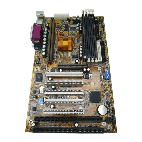
Page 12: Mainboard Layout
BX2000 3.2. MAINBOARD LAYOUT JP12 COM A COM B PS/2 Main Backup BIOS BIOS JP18 JP19 JP11 POWER Intel JP20 440BX JP21 JP17 POWER SB-LINK BANK 3 BANK 2 PIIX4 BANK 1 BANK 0 Floppy BZ 1 IDE 2 JP16 IDE 1 JP14 DRAM... - Page 13 Hardware Installation POWER FAN : POWER FAN Power Connector Pin No. Function GND. +12V SENSE PANEL(SYSTEM) FAN: PANEL(SYSTEM) FAN Power Connector Pin No. Function GND. +12V SENSE J15 : System After Ac Back Open Soft Off (Default) Short Full On JP1 : Keyboard Power On Selection Pin No.
- Page 14 BX2000 SB-LINK : For PCI Sound Card Connector Pin No. Function Signal Signal Signal IR: INFRARED Connector (OPTIONAL) Pin No. Function IR DATA OUTPUT IR DATA INPUT POWER(+) JP14 : CLEAR CMOS Pin No. Function 1-2 short Clear CMOS 2-3 short Normal (Default) JP18/ JP19 : Single/Dual BIOS (OPTIONAL) Pin No.
- Page 15 Hardware Installation Pin No. Function Open Normal (Default) Short Close for Voodoo III VGA Card. JP9 : 2*11PIN Jumper − − PW P+P G− H− GN SPKR PW : Soft Power Connector Open: Normal Operation Short: Power On/Off RE : Reset Switch Open: Normal Operation Short: For Hardware Reset System P+P−P−: Power LED...
-
Page 16: Dram Installation
BX2000 H+H−: IDE Hard Disk Active LED PIN 1: LED anode (+) PIN 2: LED cathode (−) GN: Green Function Switch Open : Normal operation Short : Entering Green Mode G−G+: Green LED PIN 1 : LED anode (+) PIN 2 : LED cathode (−) 3.4. - Page 17 Hardware Installation ON: m OFF: 5 ® Pentium II / III 233 / 66MHz 266 / 66MHz 300 / 66MHz 333 / 66MHz 366 / 66MHz 400 / 66MHz 433 / 66MHz 350 / 100MHz 400 / 100MHz 450 / 100MHz 500 / 100MHz 550 / 100MHz 600 / 100MHz...
-
Page 18: Speaker Connector Installation
BX2000 M Replace only with the same or equivalent type recommended by the manufacturer. M Dispose of used batteries according to the manufacturer’ s instructions. 3.7. SPEAKER CONNECTOR INSTALLATION There is a speaker in AT system for sound purpose. The 4 - Pins connector SPKR is used to connect speaker. - Page 19 Hardware Installation The main board supports PS/2 Mouse. The BIOS will auto detect whether the PS/2 Mouse is installed or not & assign IRQ12 for PS/2 Mouse port if it is installed. After installing the peripheral device, the user should check everything again, and prepare to power-on the system.
-
Page 20: Bios Configuration
BIOS Configuration 4.BIOS CONFIGURATION Award's BIOS ROM has a built-in Setup program that allows users to modify the basic system configuration. This type of information is stored in battery- backed CMOS SRAM so that it retains the Setup information when the power is turned off. -
Page 21: Getting Help
BX2000 4.3. GETTING HELP 4.3.1. Main Menu The on-line description of the highlighted setup function is displayed at the bottom of the screen. 4.3.2. Status Page Setup Menu / Option Page Setup Menu Press F1 to pop up a small help window that describes the appropriate keys to use and the possible selections for the highlighted item. - Page 22 BIOS Configuration • Chipset features setup This setup page includes all the items of chipset special features. • Power management setup This setup page includes all the items of Green function features. • PNP/PCI configuration This setup page includes all the configurations of PCI & PnP ISA resources.
-
Page 23: Standard Cmos Setup Menu
BX2000 4.5. STANDARD CMOS SETUP MENU The items in Standard CMOS Setup Menu (Figure 4.2) are divided into 9 categories. Each category includes no, one or more than one setup items. Use the arrows to highlight the item and then use the <PgUp> or <PgDn> keys to select the value you want in each item. - Page 24 BIOS Configuration • Primary HDDs / Secondary HDDs The category identifies the types of hard disk from drive C to F that has been installed in the computer. There are two types: auto type, and user definable type. User type is user-definable; Auto type which will automatically detect HDD type.
- Page 25 BX2000 • Floppy 3 Mode Support (for Japan Area) Disabled Normal Floppy Drive. Drive A Drive A is 3 mode Floppy Drive. Drive B Drive B is 3 mode Floppy Drive. Both Drive A & B are 3 mode Floppy Drives. •...
- Page 26 BIOS Configuration All, But Disk/Key The system boot will not stop for a keyboard or disk error; it will stop for all other errors • Memory The category is display-only which is determined by POST (Power On Self Test) of the BIOS. Base Memory The POST of the BIOS will determine the amount of base (or conventional) memory installed in the system.
- Page 27 BX2000 address space. This is memory that can be used for different applications. DOS uses this area to load device drivers to keep as much base memory free for application programs. Most use for this area is Shadow RAM.
-
Page 28: Bios Features Setup
BIOS Configuration 4.6. BIOS FEATURES SETUP Figure 4.3: BIOS Features Setup R System will detect automatically and show up when you install the Pentium III processor. • Virus Warning If it is set to enable, the category will flash on the screen when there is any attempt to write to the boot sector or partition table of the hard disk drive. - Page 29 BX2000 • CPU Internal Cache / External Cache These two categories speed up memory access. However, it depends on CPU / chipset design. The default value is Enabled. Enabled Enable cache Disabled Disable cache • CPU L2 Cache ECC Checking The default value is Disabled.
- Page 30 BIOS Configuration • Boot From LAN First The default value is Enabled. Auto Enable Boot From LAN First Function Enabled Enable Boot From LAN First Function Disabled Disable Boot From LAN First Function +You can set “ Auto” or “ Enabled” to boot from LAN first. •...
- Page 31 BX2000 • Boot Up NumLock Status The default value is On. Keypad is number keys Keypad is arrow keys • Typematic Rate Setting The default value is Disabled. Enabled Enable Keyboard Typematic rate setting. Disabled Disable Keyboard Typematic rate setting. •...
- Page 32 BIOS Configuration • PCI/VGA Palette Snoop The default value is Disabled. Enabled For having Video Card on ISA Bus and VGA Card on PCI Bus. Disabled For VGA Card only. • Assign IRQ For VGA The default value is Enabled. Enabled Assign a specific IRQ for VGA Disabled...
-
Page 33: Chipset Features Setup
BX2000 4.7. CHIPSET FEATURES SETUP Figure 4.4: Chipset Features Setup • Reset Case Open Status (Optional) • Case Opened (Optional) If the case is closed, “ Case Opened” will show “ No” . If the case have been opened, “ Case Opened” will show “ Yes” . If you want to reset “... - Page 34 BIOS Configuration • Shutdown Temp. (°C / °F) (Optional) (This function will be effective only for the operating systems that support ACPI Function.) The default value is 75°C / 167°F Disabled Normal Operation 60°C / 140°F Monitor CPU Temp. at 60°C / 140°F, if Temp. > 60°C / 140°F system will automatically power off .
- Page 35 BX2000 • Fan Fail Alarm (Optional) CPU/POWER/PANEL Fan Fail Alarm Function Disabled. Fan Fail Alarm Function Enabled. • Current FAN Speed (RPM) (Optional) Detect Fan speed status automatically. • Current Voltage (v) VCORE / VGTL/ VCC3 / ±12V / ±5V / VBAT / 5VSB (Optional) Detect system’...
- Page 36 BIOS Configuration • DRAM Data Integrity Mode This value will depend on the DRAM type. Non-ECC For 64bit standard type DIMM module. For 72bit ECC type DIMM module. • System BIOS Cacheable The default value is Enabled. Enabled Enable System BIOS Cacheable. Disabled Disable System BIOS Cacheable.
-
Page 37: Power Management Setup
BX2000 Enabled Set Address=15~16MB remap to ISA BUS. • Delayed Transaction The default value is Disabled. Disabled Normal operation. Enabled For slow speed ISA device in system. • Clock Spread Spectrum The default value is Disabled. Disabled Disabled this function Enabled Enabled Clock Spread Spectrum 4.8. - Page 38 BIOS Configuration • PM Control by APM The default value is Yes. Enable software APM function. Disable software APM function. • Video off Method The default value is DPMS. BIOS will turn off V/H-SYNC when gets into V/H SYNC + Blank Green mode for Green monitor power saving.
- Page 39 BX2000 • Soft-off by PWR-BTTN The default value is Instant-Off. Instant-off Soft switch ON/OFF for POWER ON/OFF Delay 4 Sec. Soft switch ON 4sec. for POWER OFF. • System After AC Back The default value is Soft-Off. Memory This function depends on computer status Soft-Off Set System Soft-Off Status.
- Page 40 BIOS Configuration • ModemRingOn / WakeOnLan The default value is Enabled. Disabled Disable these functions. Enabled Enable these functions. • ACPI Suspend Type The default value is Power On Suspend. Power On Set ACPI Suspend Type is Power On Suspend. Suspend Suspend to Set ACPI Suspend Type is Suspend to RAM.
-
Page 41: Pnp/Pci Configuration
BX2000 The default value is Disabled. Disabled Disable this function. Enabled Enable monitor Secondary IDE 0/1 for Green event. • Floppy Disk The default value is Enabled. Disabled Disable this function. Enabled Enable monitor Floppy Disk for Green event. • Serial Port The default value is Enabled. - Page 42 BIOS Configuration Figure 4.6: PCI Slot Configuration R This item will show up when “ Used MEM base addr” has been set. • PNP OS Installed The default value is No. Enable PNP OS Installed function. Disable PNP OS Installed function. •...
-
Page 43: Load Bios Defaults
BX2000 • Used MEM Length The default value is 8K. 8K ~ 64K Select the MEM. block size. • Assign IRQ For USB The default value is Enabled. Enabled Assign a specific IRQ for USB Disabled No IRQ is assigned for USB 4.10. -
Page 44: Load Performance Defaults
BIOS Configuration 4.11. LOAD PERFORMANCE DEFAULTS Figure 4.8: Load PERFORMANCE Defaults • Load PERFORMANCE Defaults To load PERFORMANCE defaults value to CMOS SRAM, enter "Y". If not, enter "N". 4-25... -
Page 45: Integrated Peripherals
BX2000 4.12. INTEGRATED PERIPHERALS Figure 4.9: Integrated Peripherals R This item will show up when “ Keyboard Power On: Multikey” is selected. • IDE HDD Block Mode The default value is Enabled. Enabled Enable IDE HDD Block Mode Disabled Disable IDE HDD Block Mode •... - Page 46 BIOS Configuration • IDE Secondary Master PIO (for onboard IDE 2nd channel). The default value is Auto. Auto BIOS will automatically detect the IDE HDD Accessing mode. Mode0~4 Manually set the IDE Accessing mode. • IDE Secondary Slave PIO (for onboard IDE 2nd channel). The default value is Auto.
- Page 47 BX2000 • IDE Secondary Slave UDMA. The default value is Auto. Auto BIOS will automatically detect the IDE HDD Accessing mode. Disabled Disable UDMA function. • On-Chip Primary PCI IDE The default value is Enabled. Enabled Enable onboard 1st channel IDE port. Disabled Disable onboard 1st channel IDE port.
- Page 48 BIOS Configuration • Onboard Serial Port 2 The default value is 2F8/IRQ3. Auto BIOS will automatically setup the port 2 address. 3F8/IRQ4 Enable onboard Serial port 2 and address is 3F8. 2F8/IRQ3 Enable onboard Serial port 2 and address is 2F8. 3E8/IRQ4 Enable onboard Serial port 2 and address is 3E8.
- Page 49 BX2000 • Keyboard Power on The default value is POWER Key. If your keyboard have “ POWER Key” button, you can POWER Key press the key to power on your system. Disabled Disable Keyboard Power on . Multikey Enter multikey combination to Power on system. •...
-
Page 50: Spuervisor Passoword/User Password
BIOS Configuration 4.13. SUPERVISOR PASSWORD / USER PASSWORD When you select this function, the following message will appear at the center of the screen to assist you in creating a password. Figure 4.10: Password Setting Type the password, up to eight characters, and press <Enter>. The password typed now will clear the previously entered password from CMOS memory. -
Page 51: Ide Hdd Auto Detection
BX2000 4.14. IDE HDD AUTO DETECTION Figure 4.11: IDE HDD Auto Detection Type "Y" will accept the H.D.D. parameter reported by BIOS. Type "N" will keep the old H.D.D. parameter setup. If the hard disk cylinder number is over 1024, then the user can select LBA mode or LARGER mode for DOS partition larger than 528 MB. -
Page 52: Save & Exit Setup
BIOS Configuration 4.15. SAVE & EXIT SETUP Figure 4.12: Save & Exit Setup Type "Y" will quit the Setup Utility and save the user setup value to RTC CMOS SRAM. Type "N" will return to Setup Utility. 4-33... -
Page 53: Exit Without Saving
BX2000 4.16. EXIT WITHOUT SAVING Figure 4.13: Exit Without Saving Type "Y" will quit the Setup Utility without saving to RTC CMOS SRAM. Type "N" will return to Setup Utility. 4-34... - Page 54 Per FCC Part 2 Section 2. 1077(a) This equipment has been tested and found to comply with limits for a Class B digital device , Responsible Party Name: G.B.T. INC. pursuant to Part 15 of the FCC rules. These Address: 18305 Valley Blvd., Suite#A...
- Page 55 Declaration of Conformity We, Manufacturer/Importer (full address) G.B.T. Technology Träding GMbH Ausschlager Weg 41, 1F, 20537 Hamburg, Germany declare that the product ( description of the apparatus, system, installation to which it refers) Mother Board GA-BX2000 is in conformity with...
Need help?
Do you have a question about the GA-BX2000 and is the answer not in the manual?
Questions and answers