Table of Contents
Advertisement
Quick Links
KA01533G/00/EN/01.21
71529914
2021-10-11
Products
Brief Operating Instructions
Prothermo NMT81
Tank Gauging
These Instructions are Brief Operating Instructions; they are
not a substitute for the Operating Instructions pertaining to
the device.
Detailed information about the device can be found in the
Operating Instructions and the other documentation:
Available for all device versions via:
• Internet:
www.endress.com/deviceviewer
• Smart phone/tablet: Endress+Hauser Operations App
Solutions
Services
Advertisement
Table of Contents

Related Manuals for Endress+Hauser Prothermo NMT81


Summary of Contents for Endress+Hauser Prothermo NMT81
- Page 1 Operating Instructions pertaining to the device. Detailed information about the device can be found in the Operating Instructions and the other documentation: Available for all device versions via: • Internet: www.endress.com/deviceviewer • Smart phone/tablet: Endress+Hauser Operations App...
- Page 2 Prothermo NMT81 Order code: XXXXX-XXXXXX Ser. no.: XXXXXXXXXXXX Ext. ord. cd.: XXX.XXXX.XX Serial number www.endress.com/deviceviewer Endress+Hauser Operations App A0023555 Endress+Hauser...
-
Page 3: Table Of Contents
Prothermo NMT81 Table of contents Table of contents About this document ............. . 4 Document conventions . -
Page 4: About This Document
About this document Prothermo NMT81 About this document Document conventions 1.1.1 Safety symbols DANGER This symbol alerts you to a dangerous situation. Failure to avoid this situation will result in serious or fatal injury. WARNING This symbol alerts you to a dangerous situation. Failure to avoid this situation can result in serious or fatal injury. - Page 5 Prothermo NMT81 About this document Torx screwdriver Allen key Open-ended wrench 1.1.4 Symbols for certain types of information and graphics Permitted Procedures, processes or actions that are permitted Preferred Procedures, processes or actions that are preferred Forbidden Procedures, processes or actions that are forbidden...
-
Page 6: Documentation
For an overview of the scope of the associated Technical Documentation, refer to the following: • W@M Device Viewer (www.endress.com/deviceviewer): Enter the serial number from nameplate • Endress+Hauser Operations App: Enter the serial number from the nameplate or scan the 2D matrix code (QR code) on the nameplate 1.2.1 Technical Information (TI) -
Page 7: Registered Trademarks
Prothermo NMT81 Basic safety instructions Registered trademarks FieldCare ® Registered trademark of the Endress+Hauser Process Solutions AG, Reinach, Switzerland Basic safety instructions Requirements for the personnel The personnel must fulfill the following requirements for its tasks: ‣ Trained, qualified specialists must have a relevant qualification for this specific function and task. -
Page 8: Operational Safety
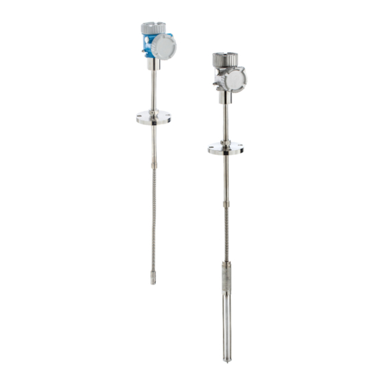
The measuring system meets the legal requirements of the applicable EU Directives. These are listed in the corresponding EU Declaration of Conformity along with the standards applied. Endress+Hauser confirms successful testing of the device by affixing to it the CE mark. Product description... - Page 9 Prothermo NMT81 Product description A0042800 1 Design of Prothermo NMT81 NMT81 with water bottom (WB) NMT81 without water bottom (WB) Converter Welded flange Adjustable flange Flexible sensor probe Water bottom (WB) sensor probe Flexible sensor probe without WB Endress+Hauser...
-
Page 10: Incoming Acceptance And Product Identification
• W@M Device Viewer (www.endress.com/deviceviewer): Enter the serial number from the nameplate • Endress+Hauser Operations App: Enter the serial number from the nameplate or scan the matrix code on the nameplate For an overview of the scope of the associated Technical Documentation, refer to the following: •... -
Page 11: Manufacturer Contact Address
WB length =: Mat.: T ≥ Ta +20K Dev.Rev.: Date: certificate: A0042783 2 Nameplate of Prothermo NMT81 Manufacturer address Order code Serial number Extended order code Intrinsically safe parameters Process temperature Maximum working pressure Length of temperature sensor probe... -
Page 12: Storage And Transport
Incoming acceptance and product identification Prothermo NMT81 Storage and transport 4.4.1 Storage conditions • Storage temperature: –40 to +85 °C (–40 to +194 °F) • Store the device in its original packaging. 4.4.2 Transporting to the measuring point CAUTION Risk of injury ‣... -
Page 13: Installation
Prothermo NMT81 Installation Installation Converter 147 (5.79) Ø100.9 96.9 (3.97) (3.81) A0045260 3 Standard converter Option 1: Converter with universal coupling 339.3 (13.36) A0047059 4 Option 1: converter (Standard G3/4 (NPT 3/4) universal coupling connection) G 1/2 dummy plug... - Page 14 α=0.00428 Ni100 GOST α=0.00617 • If elements other than the items above are required, contact your Endress+Hauser Sales Center. • NMT81 is four-wire only with MSTs (Multi-spot thermometers), but it is not compatible with a thermocouple temperature device. • The physical connection between a probe and NMT81 is completed by a zinc-plated carbon steel G 3/4"...
-
Page 15: Option 2: Converter With M20 Mounting Thread
Prothermo NMT81 Installation Option 2: Converter with M20 mounting thread This option model is designed specifically to connect with a Whessoe Varec 1700 series average temperature probe. WB data is not available because the 1700 series does not have (1.46) 182.3 (7.18) -
Page 16: Converter + Average Temperature Probe Version
Installation Prothermo NMT81 Converter + average temperature probe version Ø100.9 Ø100.9 (3.97) (3.97) Ø27.2 (1.07) Ø27.2 (1.07) Ø27.2 (1.07) A0042769 6 Converter + average temperature probe. Unit of measurement mm (in) Adjustable flange Welded flange Converter height Adjustable installation height... - Page 17 Prothermo NMT81 Installation The following tolerances are applied regardless of an optional WB probe. However, the position of the flange cannot be adjusted in a welded flange type. Probe length Tolerance of probe and element positions 1 000 to 25 000 mm (39.37 to 984.25 in) ±...
-
Page 18: Converter + Average Temperature Probe + Water Bottom Probe
Installation Prothermo NMT81 Converter + average temperature probe + water bottom probe Ø100.9 Ø100.9 (3.97) (3.97) Ø42.7 (1.68) Ø27.2 (1.07) Ø42 (1.65) A0042767 7 Converter + temperature probe + WB probe. Unit of measurement mm (in) Adjustable flange Welded flange... - Page 19 Prothermo NMT81 Installation Anchor weight hook (316L) 316L 316L PFA protection tube (thickness 1 mm (0.04 in)) Sensor pipe (304) Pt100 element Base plate/side rod (316L) Element The following tolerances are applied regardless of an optional WB probe. The position of the flange cannot be adjusted in a welding flange type.
-
Page 20: Flanges
Installation Prothermo NMT81 Flanges Welded flanges are more watertight because the joint is completely welded together. However, the position of welded flanges cannot be adjusted. Ø100.9 147 (5.79) (3.97) 96.9 (3.81) A0042770 8 Welded flange. Unit of measurement mm (in) -
Page 21: Element No. 1 Position
Prothermo NMT81 Installation Ø100.9 147 (5.79) (3.97) 96.9 (3.81) A0042793 9 Adjustable flange. Unit of measurement mm (in) Flange (JIS, ASME, JPI, DIN) Element No. 1 position Element No. 1 is mounted inside the probe according to the combinations of order specifications as described in the figure below. - Page 22 Installation Prothermo NMT81 A0045259 10 Position of NMT81 element No. 1 based on the installation method Converter + temperature probe Converter + temperature probe + WB probe Recommended installation (Probe length) Element No.1 Factory default setting distance from flange bottom to flexible probe: 215 mm (8.46 in) Minimum distance from flange bottom to upper element: 315 mm (12.40 in)
-
Page 23: Wb Probe Design
Prothermo NMT81 Installation WB probe design The integrated WB sensor (capacitance water interface measurement) is set at the bottom of an average temperature probe. The standard water interface measurement ranges are 500 mm (19.69 in), 1 000 mm (39.37 in), and 2 000 mm (78.74 in). The WB probe is made of 304 stainless pipe protected by 1 mm (0.04 in) thickness PFA tube and a 316L base plate... - Page 24 Installation Prothermo NMT81 5.8.1 Water level measurement in the three layers condition When measuring the water level with three layers (air, product, and water) present in the range of the water bottom (WB), the accuracy of the water level measurement is negatively influenced by the dielectric difference between air, product, and water.
- Page 25 Prothermo NMT81 Installation Probe length = 2.0 m Probe length = 1.0 m Probe length = 0.5 m (6.56 ft) (3.28 ft) (1.64 ft) with compensation (1.97) (-1.96) -100 (-3.94) -150 (-5.9) -200 (7.87) -250 (-9.84) -300 without compensation (-11.81) -350 (-13.78)
-
Page 26: Pre-Installation Of Nmt81
Installation Prothermo NMT81 Pre-installation of NMT81 5.9.1 Unpacking Unpack NMT81 with multiple people. If NMT81 is unpacked by one person alone, the temperature probe may become bent or twisted. A0042787 14 Unpacking NMT81 5.9.2 Temperature probe handling Do not pull the converter while holding onto the temperature probe. This may cause the device to malfunction. -
Page 27: Installation Procedure
Prothermo NMT81 Installation A0042789 16 Installation and winding of a temperature probe 600 mm (23.62 in) or more 300 mm (11.81 in) or more CAUTION If bending the temperature probe with R smaller than 300 mm (11.81 in), it may damage the probe and elements. - Page 28 Installation Prothermo NMT81 • Element intervals • The procedure for installing NMT81 will vary depending on the tank' s shape and type. A cone roof tank and a floating roof tank are used for the following examples. The procedure to mount NMT81 flange on a tank nozzle flange is the same regardless of what type of tank is being used.
- Page 29 Prothermo NMT81 Installation Flange types For NMT81 installation, there are three types of flange adjusters as follows. A0045255 18 flanges Thread type adjuster Non-height adjuster Height adjuster Adjuster NMT81 flange Tank top flange (prepared by a customer) Height adjuster type adjustment Loosen the hexagonal socket set screws [2].
- Page 30 Installation Prothermo NMT81 A0044610 19 Height adjust type of NMT81 Flange Hexagonal socket set screw Bush Endress+Hauser...
- Page 31 Prothermo NMT81 Installation Non-height adjuster type of NMT81 Make sure to align the correct orientation position of the device prior to tightening bolts. CAUTION Cable damage It may cause the damage of the cable inside. ‣ Do not rotate the housing with loosening the socket head cap screw mounted on the side of the converter.
-
Page 32: Mounting Nmt81 On A Cone Roof Tank
Installation Prothermo NMT81 5.11 Mounting NMT81 on a cone roof tank When installing a WB probe, check "zero point" (reference position) on the WB probe by comparing it to a manual dipping reference. There are three ways to install NMT81 onto a cone roof tank: •... - Page 33 Prothermo NMT81 Installation 5.11.1 Top anchor method In this method, the temperature probe or the WB probe is secured using a wire hook and a top anchor. To prevent damage to temperature probe and WB probe, ensure that they do not touch anything during insertion through the installation nozzle.
- Page 34 Installation Prothermo NMT81 Top anchor installation procedure Suspend the stranded wire from the top anchor at the top of the tank and temporarily secure its end to the top anchor. Pass the stranded wire through the wire hook at the bottom of the tank.
- Page 35 Prothermo NMT81 Installation Rotate the nuts clockwise until the top anchor' s spring is 35 to 37 mm (1.38 to 1.46 in). A0038513 23 Top anchor installation 2. Unit of measurement mm (in) Cover the top anchor. This completes the procedure for installing a top anchor.
- Page 36 Installation Prothermo NMT81 5.11.2 Stilling well method Prepare the stilling well that is larger than the diameter of the measuring probe when installing it. When using an anchor weight, use a pipe that is 100A (4") (JIS, ASME) or larger. If an anchor weight is not being used in the stilling well method, install the WB probe so that its end is below the bottom of the stilling well.
- Page 37 Prothermo NMT81 Installation 5.11.3 Anchor weight method This method secures a temperature probe using an anchor weight. To prevent damage to temperature probe and WB probe, ensure that they do not touch anything during insertion through the installation nozzle. Ø27.2 (1.07)
- Page 38 Installation Prothermo NMT81 CAUTION Installation of an anchor weight Using an anchor weight that is heavier than 6 kg (13.23 lb) may cause internal damage to the temperature probe. ‣ Ensure that the anchor weight is stable at the bottom of the tank. When installing NMT81 with a suspended anchor weight, use an anchor weight that weighs 6 kg (13.23 lb) or less.
-
Page 39: Mounting Nmt81 On A Floating Roof Tank
Prothermo NMT81 Installation 5.12 Mounting NMT81 on a floating roof tank There are three ways to mount NMT81 on to a floating roof tank. • Top anchor method • Stilling well method • Guide ring and anchor weight method If a heating coil is attached to the bottom of the tank, install NMT81 so that the bottom hook of a temperature probe or a WB probe is not too close to the heating coil. - Page 40 Installation Prothermo NMT81 150 (5.91) 20 (0.79) 300 (11.81) Ø18.2 (0.72) Ø42 (1.65) Ø27.2 (1.07) A0042758 27 Top anchor method. Unit of measurement mm (in) Distance between the base plate and the temperature probe Distance between the base plate and the WB probe...
- Page 41 Prothermo NMT81 Installation Base plate/datum plate Stranded wire Top anchor For the detailed installation procedure of top anchor, → 33 5.12.2 Stilling well method Insert a temperature probe and a WB probe into a stilling well that is 50A (2") or larger. The installation procedure is same for only temperature version.
- Page 42 Installation Prothermo NMT81 (0.79) A0042759 28 Stilling well method. Unit of measurement mm (in) Stilling well Fixed pipe Fixed pipe hole Stilling well hole (φ 25 mm (0.98 in)) Base plate/datum plate For the detailed installation procedure of stilling well,→ 36 5.12.3...
- Page 43 Prothermo NMT81 Installation 27.2 1 07) 42 (1.65) A0042760 29 Guide ring and anchor weight method. Unit of measurement mm (in) Without WB probe With WB probe Converter (electrical compartment) Flange Top element WB probe Temperature probe Element No.1 (lowest element)
- Page 44 Installation Prothermo NMT81 CAUTION Installation of an anchor weight Using an anchor weight that is heavier than 6 kg (13.23 lb) may cause internal damage to the temperature probe. ‣ Ensure that the anchor weight is stable at the bottom of the tank. When installing NMT81 with a suspended anchor weight, use an anchor weight that weighs 6 kg (13.23 lb) or less.
-
Page 45: Mounting Nmt81 On A Pressurized Tank
Prothermo NMT81 Installation 5.13 Mounting NMT81 on a pressurized tank In a pressurized tank, a protective pipe or a thermowell without any holes, slits, nor an open end must be installed in order to protect the probes from pressure. To prevent damage to temperature probe and WB probe, ensure that they do not touch anything during insertion through the installation nozzle. - Page 46 Installation Prothermo NMT81 The thermowell is installed from the top of the tank nozzle. Cover the bottom of the thermowell and weld it to protect the probe from the pressure. A0042763 31 Thermowell welding Welding point Endress+Hauser...
-
Page 47: Electrical Connection
Prothermo NMT81 Electrical connection Electrical connection NMT81 (Ex ia) intrinsically safe connection NMT81, which uses intrinsically safe HART communication, must be connected to the device' s intrinsically safe terminal. Refer to the intrinsic safety regulations for establishing wiring and field device layout. - Page 48 Electrical connection Prothermo NMT81 Connection table Connection to NRF590 Connection to NMS5 Connection to NMS8x/NMR8x/NRF81 + Terminal 24, 26, 28 + Terminal + Terminal - Terminal 25, 27, 29 - Terminal - Terminal If an analog Ex i/IS 4 to 20 mA HART module is installed, NMT81 can be connected to slot B2, B3 or C2, C3.
-
Page 49: Nmt81 Transmitter And Element Connection
Prothermo NMT81 Electrical connection NMT81 transmitter and element connection Four-wire common return enables the highest accuracy in the narrowest probe in a limited tank nozzle opening. The wiring diagram shows the configuration as follows. A0042780 33 Four-wire connection diagram... - Page 50 Electrical connection Prothermo NMT81 POWER A0038531 34 NMS8x terminal for NMT81 + terminal - terminal Endress+Hauser...
-
Page 51: Nms5 (Ex D [Ia]) Intrinsically Safe Connection
Prothermo NMT81 Electrical connection NMS5 (Ex d [ia]) intrinsically safe connection The intrinsically safe NMT81 must be connected to the intrinsically safe HART terminal on NMS5. HOIST STOP A0038529 35 NMS5 terminal Power supply Non-intrinsically safe HART communication: NRF, etc. -
Page 52: Nrf590 Terminals
Electrical connection Prothermo NMT81 NRF590 terminals NRF590 has three sets of intrinsically safe local HART terminals. OPT1 OPT2 OPT3 OPT4 A0038533 36 NRF590 (intrinsically safe) terminals HART sensor (mutually connected as a single HART fieldbus loop on the inside) -
Page 53: Commissioning
Prothermo NMT81 Commissioning Commissioning Terms related to temperature measurement A0042786 37 Terms concerning NMT81 installation Endress+Hauser... -
Page 54: Initial Setting
Commissioning Prothermo NMT81 Liquid temperature Vapor temperature Product temperature Water temperature Minimum height above tank level (uncovered) Minimum depth below tank level (covered) Minimum height above water level (uncovered) Minimum depth below water level (covered) Probe length 1st element position... - Page 55 Prothermo NMT81 Commissioning A0044582 38 Initial screen via FieldCare Device status view area Area enlarged view button for upper and lower views Upper view area Lower view area Home button Mode view Operating menu list Setting input area Area enlarged view button for descriptions...
- Page 56 Commissioning Prothermo NMT81 7.3.1 Upper and lower view areas The layout of the items in the upper view area [3] and the lower view area [4] can be changed by dragging and dropping the desired items in the display area above.
-
Page 57: Guidance
Prothermo NMT81 Commissioning Guidance Guidance contains three items: Commissioning, Calibration, andImport / Export; however this section only describes Commissioning and Import / Export. We recommend that calibration be performed by E+H service personnel, and the procedures are therefore not listed in the operating instructions. - Page 58 Commissioning Prothermo NMT81 Confirm that the device tag, name and serial number are correct, and select [Next]. A0044588 41 Device identification screen Confirm that the HART short tag, HART date code, HART descriptor are correct, and select [Next].
- Page 59 Prothermo NMT81 Commissioning Select a unit of the temperature measurement: °C, °F, and K and a unit of the distance: mm, cm, m, in, and ft. A0044590 43 Measurement adjustments screen If check [Yes] in Expert setting, go to next step and if not, skip the next step.
- Page 60 Commissioning Prothermo NMT81 Set the following values. A0045256 Select [Next]. Select each item from the Assign PV and theAssign QV, and select [Next]. A0044591 45 Output settings screen The items selected in this screen will be shown at the upper or lower view area on the initial screen.
- Page 61 Prothermo NMT81 Commissioning 10. Select [Finish] to be completed. A0044592 46 Complete screen This completes the commissioning procedure. 7.4.2 Import / Export Import / Export has three items to be set or confirmed as follows. A0044924 47...
- Page 62 Commissioning Prothermo NMT81 Save / Restore A0044921 48 Save / Restore screen Save: The information is sent to a PC from NMT81. The information of writable parameters regarding device measurements can only be saved on a PC. Saving procedure Press [Save / Restore].
- Page 63 Prothermo NMT81 Commissioning Select a desired file. Restoring starts. This completes the restoring procedure. Endress+Hauser...
- Page 64 Commissioning Prothermo NMT81 Create documentation This lists the all parameters and displays them in PDF file. A0044925 49 Create documentation screen Creating documentation procedure Press [Create documentation]. Check the required items in the Documentation window. The default setting has every item checked.
- Page 65 Prothermo NMT81 Commissioning A0045013 50 Compare datasets screen Comparing datasets procedure Press [Compare datasets]. Select a mode as the list above. Check [Show only differences] if necessary. Press [Compare]. The comparison analysis starts, and the result is shown on the window with a red diagonal line.
- Page 68 *71529914* 71529914 www.addresses.endress.com...
Need help?
Do you have a question about the Prothermo NMT81 and is the answer not in the manual?
Questions and answers