Advertisement
Quick Links
B U L L E T I N
3 3 4 4 4 4 H H
I N S T A L L A T I O N & O P E R A T I O N
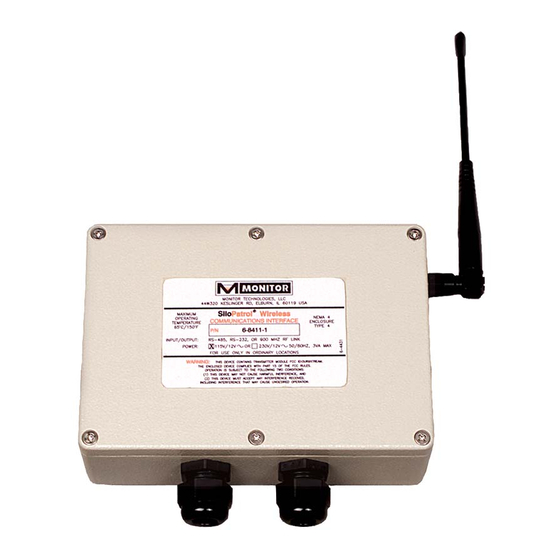
Wireless Communication Interface
S S i i l l o o
P P a a t t r r o o l l
®
Standard Antenna
Thank you for purchasing a quality product manufactured by Monitor
Technologies LLC. We realize that you do have a choice of vendors
when buying instrumentation and we sincerely appreciate you business!
This manual contains the information necessary to ensure a safe and
successful installation. Please read and comply with the section on
page 10 of this manual pertaining to SAFETY. Doing so will ensure prop-
er operation of the equipment and the safety of all personnel.
Before discarding shipping container or the internal packing materials,
please inspect the packaging thoroughly and verify that all parts are
accounted for. This product is shipped with the antenna, and mounting
plate (with its fasteners) detached from the Wireless Communication
Interface (radio module).
In the event that information contained herein does not completely sat-
isfy your requirements or answer your questions, you may contact
Technical Support on our website www.monitortech.com, by telephone
at 800-766-6486 (630-365-9403) or by fax at 630-365-5646. If your
SiloPatrol
Wireless Communications Interface ever requires service
either in or out of warranty, please contact us and obtain an RMA num-
ber prior to shipping the unit to us.
®
Advertisement

Summary of Contents for Monitor Technologies SiloPatrol
- Page 1 Technical Support on our website www.monitortech.com, by telephone at 800-766-6486 (630-365-9403) or by fax at 630-365-5646. If your SiloPatrol Wireless Communications Interface ever requires service either in or out of warranty, please contact us and obtain an RMA num- ber prior to shipping the unit to us.
- Page 2 ® SiloPatrol inventory monitor “smart” sensors (Refer to Bulletin 343A) can be used in conjunction with the SiloTrack ™ Inventory Management PC-Based Software (Refer to Bulletin 343B). Communication between the Model SMU “smart” sensors and the SiloTrack software is accomplished via 2-wire RS-485 communication format.
- Page 3 M E C H A N I C A L I N S TA L L AT I O N Communication Interface (Radio Module) Mounting: 1) Desk Top: The unit is packaged such that it can simply rest on a desktop next to the control system (i.e. SiloTrack 2) Wall mount: A universal mounting plate supplied with each Wireless Communication Interface can be...
- Page 4 E L E C T R I C A L I N S TA L L AT I O N Permanently Connected Equipment: Disconnecting devices shall be included in the system installation. The disconnects shall be within close prox- imity of the equipment, accessible to operators, and marked appropriately as the disconnect for the associated circuit.
- Page 5 Data Communications: CONNECTOR TYPE AMPHENOL NORCOMP The Wireless Communication Interface can receive data 9-pin D-sub, male con 17-DE09P 172-009-101-001 communications through one of two wiring media: either RS-485 half-duplex or RS-232. Before wiring, determine 9-pin D-sub, female con 17-DE09S 172-009-201-001 which data communication wiring medium is to be tied to 9-pin D-sub back shell 17-1724-1...
- Page 6 2) RS-485 Connection: (See Figure 9) The RS-485 pro- a) The wired circuit connecting the control system tocol permits network interconnection of multiple SiloTrack ) and the Wireless Communication devices such as the control system ( SiloTrack ), sen- Interface, sors (SMUs), Auxiliary Output Enclosures (AOEs), b) The wired circuit connecting the second Wireless Remote Display Units (RDUs) and Wireless Communi-...
- Page 7 - HKEY_CURRENT.USER jumper clip is provided for selection. Position jumper - Software clip on the two pins associated with one of three possi- - Monitor Technologies ble selections: - STCOMDRIVER RS232: Select this if the signal from the control system...
- Page 8 Support Functions: (See Figure 10) M A I N T E N A N C E 1) RUN/TEST switch: This slide switch determines mode of operation: Fuse Replacement: RUN: For normal operation of the Wireless Communi- The fuse incorporated into the Wireless Communication cation Interface, set switch in this position.
-
Page 9: Troubleshooting
3) Verify the master/slave selection settings. These T R O U B L E S H O O T I N G settings can not be identical. 4) Verify that the radio module is installed. If a radio PROBLEM: SiloTrack ™... - Page 10 Green LED: Power negligence, accident, incorrect wiring by others, or improper Housing: Powder coated die cast aluminum, installation. Monitor Technologies LLC reserves the right to IP66 NEMA 4 change the design and/or specifications without prior notice. Mounting: Desk, wall or pipe/rail M M o o n n i i t t o o r r T T e e c c h h n n o o l l o o g g i i e e s s L L L L C C 4 4 4 4 W W 3 3 2 2 0 0 K K e e s s l l i i n n g g e e r r R R d d .
Need help?
Do you have a question about the SiloPatrol and is the answer not in the manual?
Questions and answers