
Subscribe to Our Youtube Channel
Related Manuals for EUTHANEX SMARTBOX TT-4000

Summary of Contents for EUTHANEX SMARTBOX TT-4000
- Page 1 Auto CO System Tabletop System 877‐559‐0159 Toll Free Euthanex Corp. / E‐Z Systems Inc. 610‐559‐0159 Phone P.O. Box 3544 610‐821‐3061 Fax Palmer, PA 18043 www.euthanex.com info@euthanex.com ...
- Page 2 TABLE OF CONTENTS Disclaimer/ System Overview ____________________ 3 Saftey________________________________________ 4 System Setup __________________________________ 5 Operating the System ___________________________ 10 Programming the Presets ________________________ 14 Troubleshooting _______________________________ 19 EMC / EMI. This equipment has been tested and found to comply with the limits for a Class A Equipment, pursuant to part 15 of the FCC rules.
- Page 3 Parts that have failed, in whole or in part, exhibit excessive wear, are contaminated or are otherwise at the end of their useful life, should not be used and should be replaced with parts supplied by Euthanex Corporation. Tampering with the controller unit by unauthorized personnel voids all warranties and specifications. The manufacturer assumes no responsibility for any malfunction or failure of the unit if tampering is suspected.
- Page 4 The e exclamation poin nt within an equi ilateral triangle i he lightning flas sh with an arrow head intend ded to alert the u user to the presen nce of important ymbol within an equilateral trian ngle, is opera ating and mainten nance (servicing g) instructions in...
- Page 5 SYSTEM SETUP 1) The SMARTBOX TT controller is attached to the Tabletop chamber utilizing the four holes on the right side of the Chamber. Screw mounts on chamber side 2) Align the threaded nut inserts of the control box with the four holes on the right side of the chamber. Insert the M4 screws and use caution tightening them to prevent damage to the chamber. ...
- Page 6 1) Attach the supplied 1/2” check valve onto the left side of the chamber. The valve is threaded and will screw into the chamber wall. Attach the supplied 1/2” hose onto the right side of top chamber. This hose is coming off of the exhaust blower unit. The 4” hose from the blower unit can be draped to the floor, set into a hood or it can be attached to house exhaust. 2) Attach the CO2 supply from the control box to the chamber. The braided hose is already attached to the chamber, just place the quick disconnect fitting to the stem on the back side of the TT Controller. ...
- Page 7 5) Attac h the heated regulator to the CO tank . It is recomm mended that Teflon tape b be used on th e CO tank t threads befor re attaching r regulator. Us e a wrench to o tighten the mounted reg gulator. Note e: The E A‐285 Electri ically Heated Regulator is required to o operate the s system. Usin ng a non‐heat ted regula ator will likel ly result in fro ozen CO line es. 7 ...
- Page 8 Tank P Pressure Gaug ge Flow Gauge Valve B Bar Ta ank Valve 6) Plug t the regulator into an AC ou utlet. The reg gulator is the rmostatically y controlled to o automatica lly turn o on and off he at as needed to maintain C temperat ture. The larg ger gauge ind dicates the press ure from the tank. A f full tank typic cally runs at 8 800 lbs PSI. A As the tank is used, the tan nk press ure reduces a accordingly. T The regulator r flow output is indicated o...
- Page 9 8) Plug blower control cord into the SMARTBOX TT controller. Plug blower unit ac into main power source. Blower unit only operates when exhaust cycle is engaged by controller. Vent exhaust close to room return vent. 9) Plug AC cord from SMARTBOX TT controller into AC power outlet. 10) Turn on main power, ready light will come on. Setup is now complete. ...
- Page 10 OPERATING THE SYSTEM On/Off Switch 1) Press the On switch that is on the bottom of the controller. The green “READY” light will turn on. 2) Release the three latches on the front of the chamber to open the lid. ...
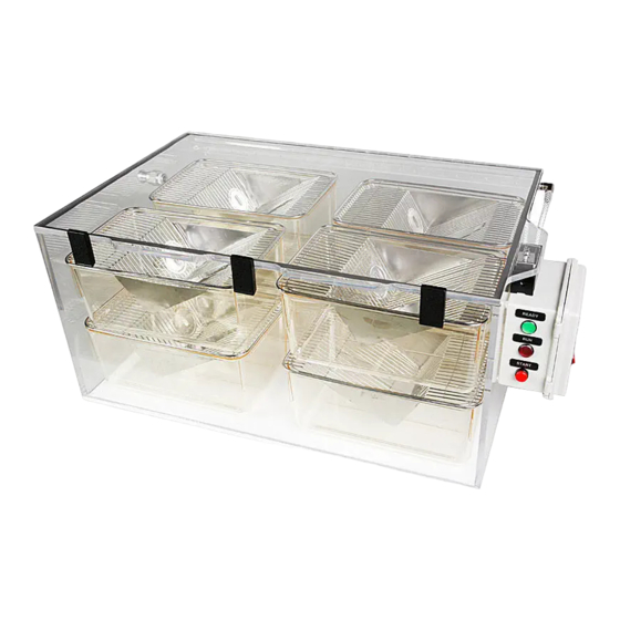
- Page 11 3) The chamber is now ready to be loaded. Cages with wire bar lids can be stacked in two layers. A TT‐8100 chamber can accommodate up to 8 standard mouse cages. A TT‐4000 chamber can accommodate up to 6 standard mouse cages. Number of cages accommodated will vary based upon actual cage size. Do not attempt to place more cages then will comfortably fit into the chamber. NOTE: Cages should be set askew to allow optimal penetration of gas to the lower cages. ...
- Page 12 4) After the chamber r is loaded, clo ose the lid an nd secure the three latche s to seal. If t the latches ar re not fully s secured, a slig ght gas leak m may occur. nk Pressure G Gauge Flow Gauge e Ta ank Valve Valve e Bar 5) Open the gas flow from the CO tank by turn ning the tank valve knob co ounterclockw wise. The larg ge PSI gauge e should be re eading 800 PS SI if the tank i is full, less if i it is not a full tank. ...
- Page 13 6) Open the gas flow out of the regulator by turning the “T” bar counterclockwise. This begins the flow of gas to the controller. Set the regulator flow rate at 50 CFH for the TT‐8100 or 33 CFH for the TT‐ 4000. 7) The system has two preset timers for species selection. Press up for “ADULTS” or down for “NEONATES” on the front of side control box. The red “RUN” light indicates the euthanasia cycle is operating. Adult Start Toggle Neonates 8) During the first initial run, adjust the regulator flow rate to 50 CFPH. This adjustment will assure a humane process. Animals will first be anesthetized with minimal stress and then euthanized while asleep. Exceeding this flow rate may introduce stress to animals and result in operation outside of AVMA guidelines. (This regulator adjustment is typically only required the first time using the system and when a full CO tank is first put on line.) 9) The system will cycle through two stages: Stage 1 Charging: Gas flows through the chamber for 8:30 minutes, fully charging the chamber with CO . Stage 2 Dwell: Gas flow stops and the chamber remains fully charged with CO for 5 minutes. Stage 3 Exhaust: Blower will activate for 3.5 minutes, chamber will unlock and return to ready state (green). ...
- Page 14 Recomm mended flow rates and pre eset times w were determin ned with ext tensive testin ng done by E Euthanex Corporat tion and are d designed to comply with h the latest g guidelines of f the AVMA A Panel on Eu uthanasia.
- Page 15 5. The c ursor will blin nk for the “T” settings. a. U se the up/do own keys to in ncrease or de crease the va alue. b. U se the right/l left keys to m move the curso or to the next t number you u would like t o change. c. A fter the desir red time is set t, press OK. Note: On nly the T = 0 00:00m will be set. The e Ta = 00:00 0 is not a pro ogrammable...
- Page 16 F series IDEC or Siemens: 1. Release the two latches to open the controller door. 2. The clock screen is on the PLC. 3. To change the preset cycle times, press ESC, then OK. The option screen will appear. 4. Press the down button , to move the arrow to: “> Program”. Press OK. 5. Press the down button , to move the arrow to: “> Set Parameter”. Press OK. 6. The password screen appears. Use the up/dw and Rt/Lt arrow to input password "CLUTCH" then hit OK 6. Timer select screen appears. This screen is maybe different that the picture based on the program loaded. ...
- Page 17 * Use the up/down keys to move to the value to change. * Press “OK” and the screen will change. Press the right arrow until s large box will be over the timer. * Press “OK” and the box will become small and over the first value of the timer. * Use the right/left keys to move the cursor to the number you would like to change. * Use the up/down keys to increase or decrease the value. * Use the right/left keys to move the cursor to the number you would like to change. * After the proper time is set, press OK. The box will change back to large. Note: only the T = 00:00m will be set. The Ta = 00:00 is not a programmable function. 6. After setting the timers, press the “ESC” button to return to the main screen. Use the up key to move to start, hit "OK" button, use left arrow to move to Yes, Hit "OK" button. The Lab Control Unit is now ready to operate. Close and latch the door. ...
- Page 18 Operational Parameters TT-8100 Factory settings for presets are: Adult Charging: 8:30 minutes Dwell: Adult 5 minutes Dwell: Neonates 59 minutes Exhaust 3:30 minutes Set regulator to 50CFH Flow meter to 25LPM TT-4000 Factory settings for presets are: Adult Charging: 8:30 minutes Dwell: Adult 5 minutes Dwell: Neonates...
- Page 19 4) It may be necessary to revise settings for the particular species that you are having difficulties with. Try extending flow and dwell times. See page 14 for instructions on changing presets. Note; If the unit does not have the exhaust blower option , the blower time needs to be set at 00:00 If this troubleshooting guide does not resolve your problem, contact Euthanex Tech Support 1‐877‐559‐0159 Toll Free Euthanex Corp. / E‐Z Systems 610‐559‐0159 Phone P.O. Box 3544 ...
Need help?
Do you have a question about the SMARTBOX TT-4000 and is the answer not in the manual?
Questions and answers