
Related Manuals for Travel Vision DDS

Summary of Contents for Travel Vision DDS
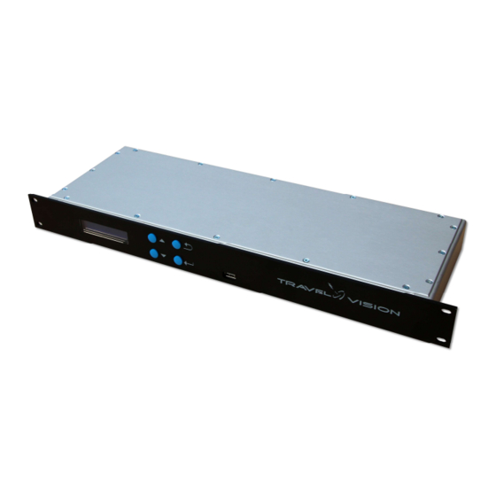
- Page 1 www.travel-vision.com Dish Diversity Switch INSTALLATION & USER’S MANUAL Version 3.3 as from software 1.0.13 October 2018...
- Page 2 The Travel Vision Dish Diversity Switch was developed to fit the needs of ship owners to have an antenna switch that also does not depend on the brand and type of satellite antennas.
-
Page 3: Table Of Contents
Content 1. System description page 4. 2. Hardware installation page 5. 2.1 General Installation page 5. 2.2 Coax cable routing page 5. 2.3 Wiring schematic page 6. 3. Installation and configuration page 7. 3.1 Equalise power levels Dish 1 and 2. page 7. -
Page 4: System Description
1. System Description Travel Vision’s Dish Diversity Switch was developed to fit the needs of ship owners to have an antenna switch that does not depend on the brand and type of satellite antennas. The Travel Vision Dish Diversity Switch doesn’t need to communicate with the antenna controller units. -
Page 5: Hardware Installation
2. Hardware Installation 2.1 General Installation The Dish Diversity Switch is provided with an Euro style Power cord and plug. Before start doing any installation, please make sure main power is disconnected. The system is designed to be installed in a 19inch cabinet rack. The Dish Diversity Switch has a standard height of 1U. -
Page 6: Wiring Schematic
2.3 Wiring Schematic Page 6... -
Page 7: Installation And Configuration
3. Installation and configuration 3.1 Equalise power levels Dish 1 and 2. Before RF cables from both dishes are connected to the DDS, make sure the dBµV power levels from both dishes should be equalised in power. For example with amplifier or attenuator set both levels on 70 dBµV. -
Page 8: Default Settings
3.4 Default Settings The following settings are default. They can be changed by the user. Changing these setting will affect the systems performance. We advise not to change any settings unless you are a certified mechanic. Setting Default Auto/Manual Auto Switch Delay 0 second RF Power Threshold... -
Page 9: Menu
3.5 Menu When a key, or combination of keys is pressed an user can enter different menu functions. To enter the settings menu, press Enter for 4 seconds. To enter installation menu, press Enter and Escape together for 4 seconds. When the switch is in automatic mode you can manually select an input by pressing the UP or Down key for 4 seconds. -
Page 10: Specifications
4. Specifications Power Supply Universal 100..240 Volt AC, 50..60 Hz 25 Watt maximum Power cord plug type Euro Dimensions 19 inch rack mount, 1U height. RF detector Frequency range L-band (950..2150 MHz) Impedance 75 Ohm Connectors F-connector female (high performance type) Pass through loss <1dB typical RF level handling... - Page 11 Page 11...
-
Page 12: Warranty Conditions
Travel Vision DDS system. Should, in case of normal use of the Travel Vision DDS system, any defect occur with 12 months after installation, as a result of a manufacturing defect and/or material defect, then this defect will be resolved under the below mentioned warranty conditions.
Need help?
Do you have a question about the DDS and is the answer not in the manual?
Questions and answers