Table of Contents
Advertisement
Quick Links
Advertisement
Table of Contents

Related Manuals for Toshiba Satellite A660D Series


Summary of Contents for Toshiba Satellite A660D Series
- Page 1 User’s Manual Satellite A660/A660D Satellite Pro A660/A660D series...
-
Page 2: Table Of Contents
Table of Contents Copyright..........vi Disclaimer . - Page 3 BD-Writer drive or BD-Combo drive ......4-20 Using WinDVD BD for TOSHIBA ......4-33 Media care .
- Page 4 TOSHIBA support ........
- Page 5 Satellite A660/A660D/Satellite Pro A660/A660D Series Starting the TOSHIBA PC Health Monitor..... . F-2 Legal Footnotes Appendix G Non-applicable Icons*1 ........G-1 CPU*2.
-
Page 6: Copyright
Intel Corporation. Windows, Microsoft and Windows logo are registered trademarks of Microsoft Corporation. Bluetooth is a trademark owned by its proprietor and used by TOSHIBA under license. Photo CD is a trademark of Eastman Kodak Company. Memory Stick, Memory Stick PRO, Memory Stick PRO Duo and i.LINK are trademarks or registered trademarks of Sony Corporation. -
Page 7: Fcc Information
Only peripherals complying with the FCC class B limits may be attached to this equipment. Operation with non-compliant peripherals or peripherals not recommended by TOSHIBA is likely to result in interference to radio and TV reception. Shielded cables must be used between the external devices and the computer’s external monitor port, Universal Serial Bus... -
Page 8: Eu Declaration Of Conformity
This product is carrying the CE-Mark in accordance with the related European Directives. Responsible for CE-Marking is TOSHIBA Europe GmbH, Hammfelddamm 8, 41460 Neuss, Germany. The complete and official EU Declaration of Conformity can be found on TOSHIBA’s web site http://epps.toshiba-teg.com on the Internet. CE compliance... -
Page 9: Reach - Compliance Statement
The new European Union (EU) chemical regulation, REACH (Registration, Evaluation, Authorization and Restriction of Chemicals), entered into force on 1 June 2007. Toshiba will meet all REACH requirements and is committed to provide our customers with information about the chemical substances in our products according to REACH regulation. -
Page 10: Canadian Regulatory Information (Canada Only)
Note that Canadian Department of Communications (DOC) regulations provide, that changes or modifications not expressly approved by TOSHIBA Corporation could void your authority to operate this equipment. This Class B digital apparatus meets all requirements of the Canadian Interference-Causng Equipment Regulations. -
Page 11: Japan Regulations
Satellite A660/A660D/Satellite Pro A660/A660D Series The hookflash (timed break register recall) function is subject to separate national type approvals. It has not been tested for conformity to national type regulations, and no guarantee of successful operation of that specific function on specific national networks can be given. Japan regulations Region selection If you are using the computer in Japan, technical regulations described in... - Page 12 FCC. In the event repairs are ever needed on your modem, they should be performed by TOSHIBA Corporation or an authorized representative of TOSHIBA Corporation.
-
Page 13: Instructions For Ic Cs-03 Certified Equipment
Satellite A660/A660D/Satellite Pro A660/A660D Series Disconnection If you should ever decide to permanently disconnect your modem from its present line, please call the telephone company and let them know of this change. Fax branding The Telephone Consumer Protection Act of 1991 makes it unlawful for any person to use a computer or other electronic device to send any message via a telephone fax machine unless such message clearly contains in a margin at the top or bottom of each transmitted page or on the first page of... -
Page 14: Notes For Users In Australia And New Zealand
Satellite A660/A660D/Satellite Pro A660/A660D Series 2. The user manual of analog equipment must contain the equipment’s Ringer Equivalence Number (REN) and an explanation notice similar to the following: The Ringer Equivalence Number (REN) of the modem, which can vary. For the REN of your modem, refer to your modem’s label. The Ringer Equivalence Number (REN) assigned to each terminal device provides an indication of the maximum number of terminals allowed to be connected to a telephone interface. - Page 15 Satellite A660/A660D/Satellite Pro A660/A660D Series Notes for use of this device in New Zealand ■ The grant of a Telepermit for a device in no way indicates Telecom acceptance of responsibility for the correct operation of that device under all operating conditions. In particular the higher speeds at which this modem is capable of operating depend on a specific network implementation which is only one of many ways of delivering high quality voice telephony to customers.
- Page 16 Satellite A660/A660D/Satellite Pro A660/A660D Series ■ When used in the Auto Answer mode, the S0 register must be set with a value of 3 or 4. This ensures: a/ A person calling your modem will hear a short burst of ringing before the modem answers.
-
Page 17: Following Information Is Only Valid For Eu-Member States
For more detailed information about the collection and recycling programmes available in your country, please visit our website (http://eu.computers.toshiba-europe.com) or contact your local city office or the shop where you purchased the product. Disposal of batteries and/or accumulators... -
Page 18: Disposing Of The Computer And The Computer's Batteries
Satellite A660/A660D/Satellite Pro A660/A660D Series Disposing of the computer and the computer's batteries ■ Discard this computer in accordance with applicable laws and regulations. For further information, contact your local government. ■ This computer contains rechargeable batteries. After repeated use, the batteries will finally lose their ability to hold a charge and you will need to replace them. -
Page 19: Optical Disc Drive Safety Instructions
Satellite A660/A660D/Satellite Pro A660/A660D Series Optical disc drive safety instructions TEAC DVD Super Multi with Double Layer Recording DV-W28S ■ The DVD Super Multi drive model employs a laser system. To ensure proper use of this product, please read this instruction manual carefully and retain for future reference. - Page 20 Satellite A660/A660D/Satellite Pro A660/A660D Series Panasonic System Networks DVD Super Multi UJ890 ■ BD-Combo UJ141 ■ BD-Writer UJ240 ■ Panasonic System Networks Co., Ltd. HITACHI-LG Data Storage, Inc. DVD Super Multi GT30N/GT30F ■ Hitachi-LG Data Storage, Inc. 22-23,KAIGAN 3-CHOME, MINATO-KU,TOKYO,108-0022 JAPAN User’s Manual...
-
Page 21: International Precautions
Satellite A660/A660D/Satellite Pro A660/A660D Series International precautions CAUTION: This appliance contains a laser system and is classified as a “CLASS 1 LASER PRODUCT.” To use this model properly, read the instruction manual carefully and keep this manual for your future reference. In case of any trouble with this model, please contact your nearest “AUTHORIZED service station.”... - Page 22 Satellite A660/A660D/Satellite Pro A660/A660D Series OBS! Apparaten innehåller laserkomponent som avger laserstråining överstigande gränsen för laserklass 1. VAROITUS. Suojakoteloa si saa avata. Laite sisältää laserdiodin, joka lähetää näkymätöntä silmilie vaarallista lasersäteilyä. CAUTION: USE OF CONTROLS OR ADJUSTMENTS OR PERFORMANCE OF PROCEDURES OTHER THAN THOSE SPECIFIED IN THE OWNER’S MANUAL MAY RESULT IN HAZARDOUS RADIATION EXPOSURE.
-
Page 23: Preface
Preface Congratulations on your purchase of the Satellite A660/Pro A660/ A660D/Pro A660D Series computer. This powerful notebook computer provides excellent expansion capability, includes multimedia functionality, and is designed to provide years of reliable, high-performance computing. This manual tells how to set up and begin using your Satellite A660/A660D/Satellite Pro A660/A660D Series computer. - Page 24 Satellite A660/A660D/Satellite Pro A660/A660D Series Icons Icons identify ports, dials, and other parts of your computer. The indicator panel also uses icons to identify the components it is providing information Keys The keyboard keys are used in the text to describe many computer operations.
- Page 25 Satellite A660/A660D/Satellite Pro A660/A660D Series Terminology This term is defined in this document as follows: Start The word "Start" refers to the " " button in Windows 7. HDD or Hard disk Some models are equipped with a "Solid State drive Drive (SSD)"...
-
Page 26: General Precautions
General Precautions TOSHIBA computers are designed to optimize safety, minimize strain and withstand the rigors of portability. However, certain precautions should be observed to further reduce the risk of personal injury or damage to the computer. Be certain to read the general precautions below and to note the cautions included in the text of the manual. -
Page 27: Creating A Computer-Friendly Environment
Satellite A660/A660D/Satellite Pro A660/A660D Series Creating a computer-friendly environment Place the computer on a flat surface that is large enough for the computer and any other items you are using, such as a printer. Leave enough space around the computer and other equipment to provide adequate ventilation. -
Page 28: Pressure Or Impact Damage
Satellite A660/A660D/Satellite Pro A660/A660D Series Pressure or impact damage Do not apply heavy pressure to the computer or subject it to any form of strong impact as this can damage the computer's components or otherwise cause it to malfunction. ExpressCard overheating Some ExpressCards can become hot during prolonged use which may result in errors or instability in the operation of the device in question. -
Page 29: Equipment Checklist
Some of the features described in this manual may not function properly if you use an operating system that was not pre-installed by TOSHIBA. Equipment checklist Carefully unpack your computer, taking care to save the box and packaging materials for future use. - Page 30 ■ TOSHIBA Recovery Media Creator ■ TOSHIBA DVD PLAYER ■ Corel Label@Once (preinstalled with some models) ■ Corel DVD MovieFactory for TOSHIBA (preinstalled with some models) ■ WinDVD BD for TOSHIBA (preinstalled with some models) ■ TOSHIBA Assist ■ TOSHIBA ConfigFree™...
- Page 31 Getting Started Getting Started ■ All users should be sure to read the section Starting up for the first time. ■ Be sure to read the enclosed Instruction Manual for Safety and Comfort for information on the safe and proper use of this computer. It is intended to help you be more comfortable and productive while using a notebook computer.
- Page 32 ■ Always use the TOSHIBA AC adaptor that was included with your computer, or use AC adaptors specified by TOSHIBA to avoid any risk of fire or other damage to the computer. Use of an incompatible AC adaptor could cause fire or damage to the computer possibly resulting in serious injury.
- Page 33 Getting Started 1. Connect the power cord to the AC adaptor. Figure 1-1 Connecting the power cord to the AC adaptor (2-pin plug) Figure 1-2 Connecting the power cord to the AC adaptor (3-pin plug) Either a 2-pin or 3-pin adaptor/cord will be included with the computer depending on the model.
- Page 34 Getting Started 3. Plug the power cord into a live wall outlet - the Battery and DC IN indicators on the front of the computer should glow. Opening the display The display panel can be opened to a wide range of angles for optimal viewing.
- Page 35 Getting Started ■ Be careful not to open the display panel too far as this could put stress on the display panel’s hinges and cause damage. ■ Do not press or push on the display panel. ■ Do not lift the computer by the display panel. ■...
- Page 36 Getting Started 1. Power button Figure 1-5 Turning on the power Starting up for the first time The Windows 7 Startup Screen will be the first screen displayed when you turn on the power. Follow the on-screen instructions on each screen in order to properly install the operating system.
- Page 37 Getting Started ■ Make sure the Hard Disk Drive/Optical Disc Drive indicators are off. If you turn off the power while a disk (disc) is being accessed, you may lose data or damage the disk. ■ Never turn off the power while an application is running. Doing so could cause loss of data.
- Page 38 Getting Started ■ When the AC adaptor is connected, the computer will go into Sleep Mode according to the settings in the Power Options (to access it, Start → → → Control Panel System and Security Power Options). ■ To restore the operation of the computer from Sleep Mode, press and hold the power button or any key on the keyboard for a short amount of time.
- Page 39 Getting Started Sleep Mode limitations Sleep Mode will not function under the following conditions: ■ Power is turned back on immediately after shutting down. ■ Memory circuits are exposed to static electricity or electrical noise. Hibernation Mode The Hibernation Mode feature saves the contents of memory to the hard disk drive when the computer is turned off so that, the next time it is turned on, the previous state is restored.
- Page 40 Getting Started Automatic Hibernation Mode The computer can be configured to enter Hibernation Mode automatically when you press the power button or close the lid. In order to define these settings, you can follow the steps as described below: 1. Click Start and click the Control Panel. 2.
-
Page 41: System Recovery Options
Getting Started System Recovery Options There is a hidden partition allocated on the hard disk drive for the System Recovery Options. This partition stores files which can be used to repair the system in the event of a problem. The System Recovery Options feature will be unusable if this partition is deleted. -
Page 42: System Recovery
Getting Started System Recovery This section describes the creation of Recovery Media and their use. Creating Recovery Media This section describes how to create Recovery Media. ■ Be sure to connect the AC adaptor when you create Recovery Media. ■ Be sure to close all other software programs except the Recovery Media Creator. - Page 43 Getting Started 4. Double click the Recovery Media Creator icon on the Windows 7 desktop, or select the application from Start Menu. 5. After Recovery Media Creator starts, select the type of media and the title you wish to copy, and then click the Create button. Restoring the pre-installed software from the Recovery hard disk drive A portion of the total hard disk drive space is configured as a hidden...
- Page 44 2. While holding down F12 key on the keyboard, turn on your computer - when the TOSHIBA Leading Innovation >>> logo screen appears, release the F12 key. 3. Use the up and down cursor key to select the appropriate option from the menu according to your actual recovery media.
-
Page 45: Chapter 2 The Grand Tour
Chapter 2 The Grand Tour This chapter identifies the various components of the computer - it is recommended that you become familiar with each before you operate the computer. Legal Footnote (Non-applicable Icons) For more information regarding Non-applicable Icons, please refer to the Legal Footnotes section in Appendix G or click the *1 above. - Page 46 The Grand Tour Infrared Receiver This is a sensor window that receives signals Window from the remote control which is provided with your computer. Bridge media slot This slot lets you insert an SD™/SDHC™/SDXC™ memory card, Memory ® Stick (PRO™), xD-Picture Card™ and MultiMediaCard™.
-
Page 47: Right Side
The Grand Tour Right side The following figure shows the computer’s right side. 1. Headphone jack 4. Optical Disk Drive 2. Microphone jack 5. DC IN 19V jack 3. USB 2.0 ports (x2) 6. Security lock slot Product appearance depends on the model you purchased. Figure 2-2 The right side of the computer Headphone jack This jack lets you connect digital speakers or a... -
Page 48: Left Side
The Grand Tour Optical Disk Drive The computer may be configured with a BD- Writer, BD-Combo or DVD Super Multi drive. DC IN 19V jack The AC adaptor connects to this jack in order to power the computer and charge its internal batteries. - Page 49 The Grand Tour TV Tuner jack TV Tuner enables watching and recording TV programs. Some models are equipped with the TV Tuner. Modem jack The modem jack allows you use to attach a modular cable in order to connect the internal modem directly to a telephone line.
-
Page 50: Back
The Grand Tour HDMI out port HDMI out port can connect with Type A connector HDMI cable. HDMI cable can send video and audio signals. In addition to this, it can send and receive control signals. eSATA/USB combo This Universal Serial Bus port, which complies to port the USB 2.0 standard, is provided on the right hand side of the computer. -
Page 51: Underside
The Grand Tour Underside The following figure shows the underside of the computer. You should ensure that the display is closed before the computer is turned over to avoid causing any damage. 1. Battery lock 4. Cooling vents 2. Battery pack 5. - Page 52 The Grand Tour Do not block the cooling vents. Keep foreign metal objects, such as screws, staples and paper clips, out of the cooling vents. Foreign metal objects can create a short circuit, which can cause damage and fire,possibly resulting in serious injury Memory module slot The memory module slot allows for the installation, replacement and removal of...
-
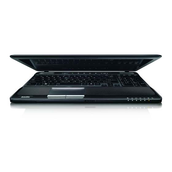
Page 53: Front With The Display Open
The Grand Tour Front with the display open This section shows the computer with the display panel open. In order to open the display, lift the display panel up and position it at a comfortable viewing angle for you. 1. Web Camera* 9. - Page 54 You can use it for video chatting or video conferences using a communication tool such as Windows Live Messenger. TOSHIBA Web Camera Application will help you to add various video effects to your video or photograph.
- Page 55 The Grand Tour Keyboard Your computer may intergrated with two kinds of keyboards: A4 size keyboard which provides the embedded numeric overlay keys, dedicated cursor control overlay keys, and Keys; full size keyboard which provides dedicated numeric keys, dedicated cursor control keys, and Keys.
-
Page 56: Indicators
The Grand Tour Indicators This section explains indicator functions. System indicators LED system indicators below their respective icons, glow when specific computer operations are in progress. Figure 2-7 System indicators DC IN The DC IN indicator normally glows white when power is being correctly supplied from the AC power adaptor. - Page 57 The Grand Tour Wireless The Wireless communication indicator blinks communication amber when the Bluetooth, Wireless LAN and Wireless WAN functions are turned on. Only some models are equipped with Bluetooth and Wireless LAN functions. Wireless WAN The Wireless WAN indicator glows or blinks blue when the Wireless WAN function is on.
-
Page 58: Optical Disc Drives
The Grand Tour CAPS LOCK This indicator glows green when letter keys are locked into their uppercase format. NUM LOCK When the NUM LOCK indicator glows, you can use the number keys on the keyboard for number entry. Optical disc drives The computer is configured with a DVD Super Multi drive or BD-Writer or BD-Combo drive. - Page 59 This section describes the types of writable CD/DVD/BD discs. Check the specifications of your drive to see the types of discs it can write. Use TOSHIBA Disc Creator to write compact discs. Please refer to Chapter 4, Operating Basics for further information.
- Page 60 The Grand Tour BD-R, BD-R(DL) discs can be written only once. The recorded ■ data cannot be erased or changed. ■ BD-RE, BD-RE(DL) discs can be recorded more than once. BD-Writer drive The full-size BD-Writer drive module lets you record data to writable CD/DVD/BD discs as well as run either 12 cm (4.72") or 8 cm (3.15") for Tray type CD/DVD/BDs without using an adaptor.
- Page 61 The Grand Tour BD-Combo drive The full-size BD-Combo drive module lets you record data to writable CD/DVDs as well as run either 12 cm (4.72") or 8 cm (3.15") for Tray type CD/DVD/BDs without using an adaptor. The read speed is slower at the centre of a disc and faster at the outer edge.
-
Page 62: Remote Controller
The Grand Tour Remote Controller A remote controller, which is provided with some models, enables you to perform some functions of your computer from a distant location. There are two different types of remote controllers: ■ Full size remote controller ■... - Page 63 The Grand Tour Full Size Remote Controller 1. Power 14. OK 2. Access indicator 15. Volume Control 3. Record 16. Channel/Page Control 4. Stop 17. Start 5. Pause 18. Mute 6. Play 19. Recorded TV 7. REW (Rewind) 20. Guide 8.
- Page 64 The Grand Tour Power Starts or terminates the operating system. This button functions like the Power button of your computer. By default, the Sleep Mode is equivalent to the Power Off state of your computer. To change the setting, click Start, select Control panel →...
- Page 65 The Grand Tour Selects the desired action or window option. It acts like the ENTER Key. If watching TV in full screen mode, pressing OK switches back to the previous viewed channel. Press again to toggle back. It acts the same way as a Jump button on some TV remote controls.
- Page 66 The Grand Tour Red, Green, Yellow It jumps to a registration link. and Blue buttons These buttons are not provided with some models. Teletext Starts or terminates the Teletext mode. This button is not provided with some models. Slim Size Remote Controller 1.
- Page 67 The Grand Tour DVD Menu Opens the main menu on a DVD movie, if available. Start Opens Media Center to the main window. Power Starts or terminates the operating system. This button functions like the Power button of your computer. By default, the Sleep Mode is equivalent to the Power Off state of your computer.
-
Page 68: Using The Remote Controller
The Grand Tour Volume - Decreases the volume while viewing DVD/BD or replaying CD. Mute Turns your computer sound on/off. Brightness down Decreases the computer's display panel brightness in individual steps. Using the Remote Controller Some computers include a remote control unit, which allows you to control some of your computer’s functions from a distant location. -
Page 69: Installing/Removing Batteries
The Grand Tour 15˚ 15˚ Figure 2-12 Operational range of the remote control * The appearance of the provided Remote Controller may vary from model to model. Even if the remote controller is within the effective range as described above, it may malfunction or not work correctly in the following cases. ■... - Page 70 The Grand Tour Store the battery for the remote control beyond the reach of children. If a child swallows a battery, this might result in choking. If it happens, contact a doctor immediately. Observe the following precautions when using the battery of the Remote Controller.
- Page 71 The Grand Tour 2. Insert the batteries in place. Be sure to place the batteries with their polarities (+ and -) in the correct position. Figure 2-14 Inserting the batteries 3. Close the battery cover. Close the cover securely until it clicks. Figure 2-15 Closing the battery cover Replacing the batteries When the batteries in the Remote Controller reach the end of their life, the...
- Page 72 The Grand Tour Type of battery that can be used for the Slim Size Remote Controller When the batteries shipped with the Remote Controller are discharged, replace them with commercially available CR2016 Lithium batteries. Other types or battery should not be used. Installing the battery 1.
- Page 73 The Grand Tour Figure 2-20 Removing the batteries 3. Insert the battery in place. Be sure to place the batteries with correct polarities. Press the battery down to the stopper then push it forward to fit into the battery case. 4.
-
Page 74: Ac Adaptor
The Grand Tour Figure 2-22 Removing a Slim size remote controller AC adaptor The AC adaptor can automatically adjust to any voltage ranging from 100 to 240 volts and to a frequency of either 50 or 60 hertz, enabling you to use this computer in almost all country/region. - Page 75 Always use the TOSHIBA AC adaptor that was included with your computer, or use AC adaptors specified by TOSHIBA to avoid any risk of fire or other damage to the computer. Use of an incompatible AC adaptor could cause fire or damage to the computer possibly resulting in serious injury.
-
Page 76: Nvidia® 3D Visiontm
The Grand Tour NVIDIA® 3D VISION NVIDIA® 3D Vision™, which is provided with some models, enables 3D Vision feature on your computer. Detail usage of the 3D Vision, please refer to "3D Vision™ QUICK START GUIDE" in 3D Vision box. Read the "SAFETY INFORMATION"... - Page 77 The Grand Tour 4. Select your gaming environment. 5. 3D Ready display is found. 6. Turn on your glasses. 7. Test your hardware setup. This screen is used to verify that your hardware is properly configured to view stereoscopic 3D effects and that your glasses and emitter are functioning properly.
-
Page 78: Chapter 3 Hardware, Utilities And Options
Your computer is equipped with one processor and processor type varies depending on model. To check which type of processor is included in your model, open the TOSHIBA PC Diagnostic Tool Utility by clicking Start → All Programs → TOSHIBA → Utilities → PC Diagnostic Tool. - Page 79 Hardware, Utilities and Options Memory Memory slots 1 GB, 2 GB or 4 GB memory modules can be installed in the computer's two memory slots for a maximum of 8,192MB system memory. This computer can be equipped with memory modules of a maximum size of 8,192MB. The actual amount of useable system memory will be less than the installed memory modules.
- Page 80 Hardware, Utilities and Options Legal Footnote (Battery Life) For more information regarding Battery Life, please refer to the Legal Footnotes section in Appendix G or click the *4 above. RTC battery The internal RTC battery backs up the Real Time Clock (RTC) and calendar.
- Page 81 Hardware, Utilities and Options Optical disc drive Drive The following optical disc drive may be pre- installed in this computer. ■ DVD Super Multi drive Double Layer ■ DVD Super Multi drive with Labelflash ■ BD-Writer drive ■ BD-Combo drive Display The computer's internal display panel supports high-resolution video graphics and can be set to a wide range of viewing angles for maximum...
- Page 82 Hardware, Utilities and Options ® Vari-Bright™ ® AMD chipset model may include the AMD Vari-Bright™ feature that can save the computer's power consumption by optimizing picture contrast on the internal LCD. This feature can be used if the computer is: ■...
- Page 83 Hardware, Utilities and Options ■ Please use the default setting for NVIDIA Optimus technology. ■ If the program does not run normally after the setting has been changed, please restore the program to the default setting. ■ If the program does not run normally, please restore the preferred graphics processor to the default setting.
- Page 84 Hardware, Utilities and Options 3D Program Override Settings 1. Click Start → Control Panel → NVIDIA Control Panel. 2. Expand the 3D Settings category and select Manage 3D settings. 3. In the Program Settings tab, select a program to customize from the drop-down list.
- Page 85 You can use it for video chatting or video conferences using a communication tool such as Windows Live Messenger. TOSHIBA Web Camera Application will help you to add various video effects to your video or photograph.
-
Page 86: Special Features
Footnotes section in Appendix G or click the *8 above. Special features The following features are either unique to TOSHIBA computers or are advanced features which make the computer more convenient to use. Access each function using the following procedures. - Page 87 Hardware, Utilities and Options System automatic This feature automatically shuts down the system Sleep/Hibernation into either Sleep Mode or Hibernation Mode when there is no input or hardware access for a Mode specified time. This can be specified in the Power Options.
- Page 88 The TOSHIBA HDD Protection function does not guarantee that the hard disk drive will not be damaged. ■ TOSHIBA HDD Protection cannot be used in models that are equipped with SSD. Hibernation Mode This feature lets you turn off the power to the computer without exiting from your software.
-
Page 89: Toshiba Value Added Package
Refer to Appendix F, TOSHIBA PC Health Monitor. TOSHIBA Value Added Package This section describes the TOSHIBA Component features pre-installed on the computer. TOSHIBA Power TOSHIBA Power Saver provides you with the Saver features of more various power supply managements. - Page 90 Hardware, Utilities and Options TOSHIBA Button Support cannot be used in models that are not equipped with eco button and Programmable button. TOSHIBA Zooming This utility allows you to enlarge or reduce the Utility icon size on the Windows Desktop, or the zoom factor associated with specific supported applications.
-
Page 91: Utilities And Applications
This software is provided for playback of DVD- PLAYER Video. It has an on-screen interface and functions. Click Start → All Programs → TOSHIBA DVD PLAYER → TOSHIBA DVD PLAYER. For details on how to use TOSHIBA DVD PLAYER, see the help file. User’s Manual 3-14... - Page 92 Video. Power-saving features may interfere with smooth playback. ■ If you see the screen blinking while playing DVD with subtitle on at Media Player, please use TOSHIBA DVD PLAYER or Media Center to play DVD. Bluetooth Stack for This software enables communication between...
- Page 93 This utility has the function of Physical Format Utility and Write-Protect to DVD-RAM. This utility is contained the setup module of TOSHIBA Disc Creator. To start this utility, click Start → All Programs → TOSHIBA → CD&DVD Applications → DVD-RAM Utility.
- Page 94 1. Launch Corel Label@Once (the operation varies depending on the models you purchased): ■ Click Start → All Programs → DVD MovieFactory for TOSHIBA → DVD MovieFactory Launcher. Click Create Disc Label. ■ Click Start → All Programs → Corel Label@Once → Corel Label@Once.
- Page 95 Alert Utility the Disk Drive operating status and execute the system backup. To access the utility, click Start → All Programs → TOSHIBA → Utilities → HDD SSD Alert. TOSHIBA Service This application allows your computer to Station automatically search for TOSHIBA software...
-
Page 96: Optional Devices
The computer is equipped with a single ExpressCard slot into which any ExpressCard device that meets industry standards, either manufactured by TOSHIBA or another vendor, can be installed. The slot supports hot plug connection and utilizes the PCI Express interface that supports the reading and writing of data at a theoretical maximum rate of 2.5Gbps. - Page 97 Hardware, Utilities and Options 3. Insert the ExpressCard into the ExpressCard slot on the side of the computer. 4. Press the ExpressCard gently to ensure a firm connection is made. 1. ExpressCard slot 2. ExpressCard Figure 3-1 Inserting the ExpressCard 5.
-
Page 98: Bridge Media Slot
Hardware, Utilities and Options Bridge media slot The computer is equipped with a Bridge media slot that can accommodate some kinds of memory media with various memory capacities so that you can easily transfer data from devices, such as digital cameras and Personal Digital Assistants. - Page 99 Hardware, Utilities and Options Memory media This section provides the important safety precautions in order to handle your memory media. Points to note about the SD/SDHC/SDXC memory card SD/SDHC/SDXC memory cards comply with SDMI (Secure Digital Music Initiative), which is a technology adopted to prevent unlawful copy or playback of digital music.
- Page 100 Hardware, Utilities and Options Media care Observe the following precautions when handling the card. Card care ■ Do not twist or bend cards. ■ Do not expose cards to liquids or store in humid areas or lay media close to containers of liquid. ■...
- Page 101 Hardware, Utilities and Options 3. Press the memory media gently to ensure a firm connection is made. 1. Bridge media slot 2. Memory media Figure 3-4 Inserting a memory media ■ Make sure memory media is oriented properly before you insert it. If you insert the media in wrong direction, you may not be able to remove ■...
- Page 102 You can access the inserted memory modules efficiently in dual channel. ■ Use only memory modules approved by TOSHIBA. ■ Do not try to install or remove a memory module under the following conditions.
- Page 103 Hardware, Utilities and Options Point to note about memory module error If you install a memory module that is not compatible with the computer, the Power indicator will flashes (on for 0.5 seconds, off for 0.5 seconds) in the following ways; ■...
- Page 104 Hardware, Utilities and Options 6. Slide your fingernail or a thin object under the cover and lift it off. 1. Memory module cover 2. Screw Figure 3-6 Removing the memory module cover 7. Align the notch of the memory module with that of the memory slot and gently insert the module into the slot at about a 45 degree angle before holding it down until the latches on either side snap into place.
- Page 105 Hardware, Utilities and Options ■ Never allow metal objects, such as screws, staples and paper clips, to enter the computer. Foreign metal objects can create a short circuit, which can cause computer damage and fire, possibly resulting in serious injury. ■...
- Page 106 Hardware, Utilities and Options 10. Turn your computer over. 11. Turn the computer on and make sure the added memory is recognized - to confirmed it, Start → Control Panel → System and Security → System icon. Removing a memory module To remove the memory module, follow the steps as detailed below: 1.
- Page 107 Hardware, Utilities and Options 1. Latches Figure 3-9 Removing the memory module 9. Seat the memory module cover in place and secure it with one screw. Take care to ensure that the memory module cover is firmly closed. 10. Install the battery pack - refer to Replacing the battery pack section in Chapter 6, Power and Power-Up Modes, if required.
- Page 108 Hardware, Utilities and Options 2. Connect the monitor cable to the external monitor port and tighten the screws on the left and right hand side of the connector as required. 1. External monitor port 2. Monitor cable Figure 3-10 Connecting the monitor cable to the external monitor port 3.
- Page 109 Hardware, Utilities and Options 4. Turn the computer on. You can use the hotkeys Fn + F5 or use the TV-Out button to change the display device. Refer to Chapter 5, Keyboard. If a television is connected to the computer, set the TV type in Display Properties.
- Page 110 Hardware, Utilities and Options 2. Click the Advanced settings button. The Generic PnP Monitor and ® Mobile Intel Arrandale Graphics Properties dialogue box opens. 3. Click the Graphics Properties button. 4. In the subsequent dialogue box, click Display → Multiple Displays and then set up your television and notebook displays.
- Page 111 Hardware, Utilities and Options For NVIDIA 1. Right click on the computer desktop and select NVIDIA Control Panel. 2. Click Display and select Set up multiple displays. 3. Click the icon on TV and select the display mode for TV. User’s Manual 3-34...
- Page 112 Hardware, Utilities and Options For ATI 1. Click Start → All Programs → Catalyst Control Center → CCC. 2. Click Graphics and select Desktop & Displays. User’s Manual 3-35...
- Page 113 Hardware, Utilities and Options 3. Click the triangle icon on TV and select the display mode for TV. USB FDD Kit The USB floppy diskette drive accommodates either a 1.44MB or 720KB floppy diskette and connects to one of the computer's USB ports. 1.
- Page 114 Hardware, Utilities and Options Connecting the USB floppy diskette drive To connect the drive, plug the floppy diskette drive’s USB connector into a computer’s USB port. Make sure the connector is properly aligned with the socket. Do not try to force the connection, doing so can damage the connecting pins.
- Page 115 Hardware, Utilities and Options 3. Click the USB floppy diskette drive device that you want to remove. 4. Carefully pull the floppy diskette drive's USB connector out from within the computer's USB port. eSATA (External Serial ATA) An device corresponding to eSATA function can be connected to the eSATA/USB combo port on the computer.
- Page 116 Hardware, Utilities and Options Disconnecting an eSATA device When you have finished using an eSATA device, you can follow the procedures below in order to disconnect it: 1. Wait for the indicator light of an eSATA device to go out to make sure all activity has stopped.
- Page 117 Hardware, Utilities and Options Connecting the security lock In order to connect a security cable to the computer, follow the steps as detailed below: 1. Turn the computer so its back side faces you. 2. Align the security cable with the lock slot and secure it in place. 1.
-
Page 118: Optional Accessories
For reference, the following list details some of the items that are available from your reseller or TOSHIBA dealer: DDR3-1066 Memory A 1 GB, 2 GB or 4 GB memory module (DDR3- 1066) can easily be installed in the computer. -
Page 119: Chapter 4 Operating Basics
Chapter 4 Operating Basics This chapter describes the basic operations of your computer, highlights the precautions that should be taken when using it. Using the Touch Pad To use the Touch Pad, simply touch and move your fingertip across it in the direction you want the on-screen pointer to go. -
Page 120: Touch Pad Gesture
Operating Basics You can also tap the Touch Pad to perform functions similar to those of the left button on a standard mouse. Click: Tap once Double-click: Tap twice Drag and drop: Tap to select the item(s) you want to move, leave your finger on the Touch Pad after the second tap and then move the item(s) to their new destination. - Page 121 Operating Basics How to Swipe your Finger Using the following steps when swiping fingers for fingerprint registration or authentication will help to minimize authentication failures: Align the first joint of the finger to the center of the sensor. Lightly touch the sensor and swipe finger levelly towards you until the sensor surface becomes visible.
- Page 122 Operating Basics ■ Do not paste stickers or write on the sensor. ■ Do not touch the sensor with a finger or any other object which may have a build-up of static electricity on it. Observe the following before you place your finger on the sensor whether for fingerprint enrollment/registration or recognition.
- Page 123 TOSHIBA does not guarantee that the fingerprint utility technology will be completely secure or error-free, or that it will accurately screen out unauthorized users at all times. TOSHIBA is not liable for any failure or damage that might arise out of the use of the fingerprint software.
- Page 124 Delete the fingerprint data for the currently logged in user 1. Click Start → All Programs → TOSHIBA → Utilities → TOSHIBA Fingerprint Utility, or double click the utility icon in the Taskbar. 2. Swipe your finger across the fingerprint sensor.
- Page 125 7. Click Close. 8. "Are you sure you want to quit?" is displayed. Click OK. It will be returned to the TOSHIBA Fingerprint Utility main menu. Windows Logon via Fingerprint Authentication In place of the usual Windows logon by ID and password, fingerprint authentication also allows logon to Windows.
- Page 126 How to Enable Fingerprint boot authentication and Single Sign-On feature It is necessary to first enroll your fingerprint with the TOSHIBA Fingerprint Utility prior to enabling and configuring the boot authentication and Single Sign-On feature. You should check that your fingerprint is enrolled before configuring the settings.
-
Page 127: Web Camera
You can use it for video chatting or video conferences using a communication tool such as Windows Live Messenger. TOSHIBA Web Camera Application will help you to add various video effects to your video or photograph. -
Page 128: Using Toshiba Web Camera Application
When recording in dimly lit environments, select "Night Mode" which allows for brighter images with less noise. Using TOSHIBA Web Camera Application TOSHIBA Web Camera Application is pre-configured to start when you turn ® 7; if you need to restart it go to Start → All Programs →... -
Page 129: Using The Toshiba Face Recognition
Toshiba does not guarantee that the face recognition utility will accurately screen out unauthorized users at all times. Toshiba is not liable for any failure or damage that might arise out of the use of the face recognition software or utility. - Page 130 Take a picture for facial verification purposes, and register the data needed when you log in. To register the data needed when you log in, follow the steps as described below: 1. To launch this utility, click Start → All Programs → TOSHIBA → Utilities → Face Recognition. ■...
- Page 131 How to launch the help file For further information on this utility, please refer to help file. 1. To launch the help file, click Start → All Programs → TOSHIBA → Utilities → Face Recognition Help. Windows Logon via TOSHIBA Face Recognition This section explains how to login to Windows with TOSHIBA Face Recognition.
-
Page 132: Using Optical Disc Drive
Operating Basics 5. Verification will be performed. If the authentication is successful, the image data taken in step 4 will be faded in and placed over one another. ■ If an error occurs during authentication, you will be returned to the Select Tiles screen. - Page 133 Operating Basics If you have a DVD SuperMulti drive, BD-Writer drive or BD-Combo drive, refer also to the Writing CD/DVD/BD on DVD Super Multi drive or BD- Writer drive or BD-Combo drive section for precautions on writing to CD/DVD/BD. Loading discs ■...
- Page 134 Operating Basics 3. Lay the CD/DVD/BD, label side up, in the disc tray. 1. Laser lens Figure 4-6 Inserting a CD/DVD/BD When the disc tray is fully opened, the edge of the computer will extend slightly over the CD/DVD/BD tray. Therefore, you will need to turn the CD/DVD/BD at an angle when you place it in the disc tray.
- Page 135 Operating Basics 5. Push the center of the disc tray to close it. Press gently until it locks into place. If the CD/DVD/BD is not seated properly when the disc tray is closed, the CD/DVD/BD might be damaged. Also, the disc tray might not open fully when you press the eject button.
- Page 136 Operating Basics ■ Slot ODD To load CD/DVD/BD, follow the steps as listed below and refer to following figures. 1. When the computer's power is on, insert CD/DVD/BD into the ODD directly. Removing discs ■ Tray ODD To remove the CD/DVD/BD, follow the steps as detailed below: Do not press the eject button while the computer is accessing the media drive.
- Page 137 Operating Basics Figure 4-8 Removing a CD/DVD/BD 3. Push the center of the disc tray to close it. Press gently until it locks into place. ■ Slot ODD To remove a CD/DVD/BD, press eject button let CD/DVD/BD be put out. How to remove CD/DVD/BD when the disc tray will not open Pressing the eject button will not open the disc tray when the computer power is off.
-
Page 138: Writing Cd/Dvd/Bd On Dvd Super Multi Drive Or Bd-Writer Drive Or Bd-Combo Drive
CD-R/RW media cannot be accessed using the Create CD/DVD option in Media Center. ■ To write data to CD-R/-RW media, use the TOSHIBA Disc Creator feature that is installed on your computer. When writing information to media using an optical drive, you should always ensure that you connect the AC adaptor to a live power socket. - Page 139 RAM media, however, it must be noted that disc quality can affect write or rewrite success rates. Please also be aware that in no event does TOSHIBA guarantee the operation, quality or performance of any disc. DVD superMulti drive CD-R: TAIYO YUDEN CO., Ltd.
- Page 140 Operating Basics DVD-RW: DVD Specifications for Recordable Disc for Version 1.1 or version 1.2 Victor Company of Japan, Ltd. (JVC) (for 2x, 4x and 6x speed media) MITSUBISHI KAGAKU MEDIA CO., LTD. (for 2x, 4x and 6x speed media) DVD-RAM: (DVD Specifications for DVD-RAM Disc for Version 2.0, Version 2.1 or Version 2.2) Panasonic CO., LTD.
- Page 141 Operating Basics DVD-RAM: (DVD Specifications for DVD-RAM Disc for Version 2.0, Version 2.1 or Version 2.2) Panasonic CO., LTD. (for 3x and 5x speed media) Hitachi Maxell,Ltd. (for 3x and 5x speed media) BD-R: Panasonic CO., LTD. BD-R(DL): Panasonic CO., LTD. BD-RE: Panasonic CO., LTD.
- Page 142 CD/DVD/BD - do not try to write from shared devices such as a server or any other network device. ■ Writing with software other than TOSHIBA Disc Creator has not been confirmed, therefore operation with other software applications cannot be guaranteed.
- Page 143 Keep mobile phones and other wireless communication devices away from the computer. Disclaimer TOSHIBA does not bear responsibility for the following: ■ Damage to any CD-R, CD-RW, DVD-R, DVD-R (Dual Layer), DVD-RW, DVD+R, DVD+R (Double Layer), DVD+RW or DVD-RAM disc that may be caused by writing or rewriting with this product.
- Page 144 CD Player' function to record music to DVD-R, DVD-R (Dual Layer), DVD-RW, DVD+R, DVD+R (Double Layer) or DVD+RW media. ■ Do not use the 'Disc Backup' function of TOSHIBA Disc Creator in order to copy DVD-Video or DVD-ROM material that has copyright protection. ■...
- Page 145 4. Select File Open or Full Compare mode. 5. Click the OK button. How to learn more about TOSHIBA Disc Creator Please refer to the Help files for additional TOSHIBA Disc Creator information. ■ Opening the TOSHIBA Disc Creator Manual Start →...
- Page 146 How to make a DVD-Video Simplified steps for making a DVD-Video from adding video source: 1. Click Start → All Programs → DVD MovieFactory for TOSHIBA → DVD MovieFactory Launcher to launch DVD MovieFactory. 2. Insert a DVD-R, DVD+R, DVD-RW or DVD+RW disc in Burner.
- Page 147 Operating Basics ■ Make sure that your computer is running on AC power when using DVD MovieFactory. ■ Operate the computer at Full Power. Do not use power-saving features. ■ While you are editing DVD, you can display preview. However, if another application is running.
- Page 148 Some BD-Writer/BD-Combo drives for personal computers or other Blu-ray disc players may not be able to read BD-R/RE discs. TOSHIBA DVD PLAYER Please be aware of the following limitations when you use the TOSHIBA DVD PLAYER: Notes on use ■...
- Page 149 Center" to play DVD. Display Devices & Audio 1. "TOSHIBA DVD PLAYER" will only run when "Colors" is set to "True Color (32 bit)". Click Start → Control Panel → Appearance and Personalization → Display → Adjust resolution, click "Advanced settings", select "Monitor"...
- Page 150 If this occurs, select Play DVD movie, (using TOSHIBA DVD PLAYER) to launch the TOSHIBA DVD PLAYER. 2. Select Start → All Programs → TOSHIBA DVD PLAYER to start "TOSHIBA DVD PLAYER". Operating TOSHIBA DVD PLAYER Notes on Using "TOSHIBA DVD PLAYER".
-
Page 151: Using Windvd Bd For Toshiba
Please be aware of the following limitations when you use WinDVD BD for TOSHIBA: Notes on use ■ "WinDVD BD for TOSHIBA" is for Blu-ray Disc playback only. DVD playback is not supported. Please use "TOSHIBA DVD PLAYER" for DVD playback. ■... -
Page 152: Media Care
Operating Basics ■ To playback video on an external display or TV using WinDVD BD, use output devices like external displays or TV that have RGB or HDCP supported HDMI port. ■ The Blu-ray disc movie can be played only on internal LCD displays or external devices connected via an RGB and HDMI output. - Page 153 Operating Basics 4. Hold the CD/DVD/BD by its outside edge or the edge on the center hole - any fingerprints on the surface of the disc can prevent the drive from properly reading data. 5. Do not expose the CD/DVD/BD to direct sunlight, extreme heat or cold. 6.
-
Page 154: Sound System
Operating Basics Sound System This section describes some of the audio control functions. Adjusting System Volume You can control the overall level of sound using Windows Volume Mixer. To launch Volume Mixer, follow the steps below. 1. Locate the Speaker icon on the task tray. 2. - Page 155 Operating Basics ■ Microphone is the default input device. It should be selected when using the computer’s internal microphone or an external microphone connected to the Microphone and Line in jack to record sound. If an external microphone or audio cable is connected to the Microphone and Line in jack, the Realtek HD Audio Manager Connector Settings dialog will be displayed allowing selection of either "Line In"...
- Page 156 Operating Basics Dolby Advanced Audio Dolby Advanced Audio provides a stunning listening experience from any pair of speakers or headphones. Adding a new level of realism to movies, music, and games, this is the quality audio customers have been missing from your computers.
-
Page 157: Modem
Operating Basics Modem This section describes how to connect and disconnect the internal modem to and from a telephone jack. ■ Connection to any communication line other than an analog phone line could cause a computer system failure. ■ Connect the built-in modem only to ordinary analog phone lines. ■... - Page 158 Operating Basics Please check whether the region that you are going to select is supported region by this PC before selecting the region. If you select the region that is not supported, the local setting of the modem is set to the United States. Properties menu Click the icon with the secondary (right) mouse button in order to display a Properties menu on the screen.
- Page 159 Operating Basics Connecting the modular cable To connect the modem's modular cable, follow the steps as detailed below: ■ Connection to any communication line other than an analog phone line could cause a computer system failure. ■ Connect the built-in modem only to ordinary analog phone lines. ■...
-
Page 160: Wireless Communications
Operating Basics Disconnecting the modular cable To disconnect the modular cable, follow the steps as detailed below: 1. Pinch the lever on the plug in the telephone jack and pull it out from within the connector. 2. Pinch the lever on the plug in the computer's modem jack and pull it out from within the computer. - Page 161 ■ TOSHIBA is not liable for the loss of data due to eavesdropping or illegal access through the wireless LAN and the damage thereof. Bluetooth wireless technology...
- Page 162 This Bluetooth Stack is based on the Bluetooth Version 1.1/1.2/2.0+EDR/2.1+EDR specification. However, TOSHIBA cannot confirm the compatibility between any computing products and/or other electronic devices that use Bluetooth, other than TOSHIBA notebook computers. Release Notes related to the Bluetooth Stack for Windows by TOSHIBA 1.
-
Page 163: Lan
Operating Basics Wireless communication Indicator The wireless communication indicator shows the status of the computer's wireless communication functions. Indicator status Indication Indicator off The wireless communication switch is off - no wireless functionality is available. Indicator glows Wireless communication switch is on. Except for the stopped device by the software switch, all the wireless-communications functions can output a radio wave. - Page 164 Operating Basics If you are using Ethernet LAN (10 megabits per second, 10BASE-T), you can connect with a CAT3 or higher cable. Connecting the LAN cable To connect the LAN cable, follow the steps as detailed below: ■ Connect the AC adaptor before connecting the LAN cable. The AC adaptor must remain connected during LAN use.
-
Page 165: Computer Handling
Operating Basics Disconnecting the LAN cable To disconnect the LAN cable, follow the steps as detailed below: Make sure the LAN Active indicator (amber LED) is out before you disconnect the computer from the LAN. 1. Pinch the lever on the connector in the computer’s LAN jack and pull out the connector. -
Page 166: Using The Hard Disk Drive (Hdd) Protection
The TOSHIBA HDD Protection function does not guarantee that the hard disk drive will not be damaged. ■ TOSHIBA HDD Protection cannot be used in models that are equipped with SSD. When vibration is detected, a message will be displayed on the screen, and the icon in the Taskbar notification area will change to the protection state. - Page 167 TOSHIBA HDD Protection is disabled. TOSHIBA HDD Protection Properties You can change the TOSHIBA HDD Protection settings by using the TOSHIBA HDD Protection Properties window. To open the window, click Start → All Programs → TOSHIBA → Utilities → HDD Protection Settings.
-
Page 168: Using The Toshiba Sleep Utility
Intensely shaking the computer or other subjecting it to strong impacts may cause damage to the computer. Details To open the Details window, click the Setup Detail button in the TOSHIBA HDD Protection Properties window. Detection Level Amplification When the AC adaptor is disconnected or the lid is closed, HDD Detection assumes that the computer will be carried and sets the detection level to the maximum for 10 seconds. - Page 169 Operating Basics ■ When Sleep and Charge function is enabled, USB bus power (DC5V) will be supplied to compatible ports even when the power of the computer is turned OFF. USB bus power (DC5V) is similarly supplied to the external devices which are connected to the compatible ports.
- Page 170 ■ Use the "Sleep and Music" feature with the display open. Starting the TOSHIBA Sleep Utility To start the utility, click Start → All Programs → TOSHIBA → Utilities → Sleep Utility. Enabling Sleep and Charge You can enable Sleep and Charge by marking the "Enable Sleep and Charge"...
-
Page 171: Heat Dispersal
Operating Basics Enable under Battery Mode You can enable to use Sleep function(s) only with the embedded battery pack (without AC adapter connected) by marking the "Enable under Battery Mode" check box and clicking the Apply button. "Enable under Battery Mode"... -
Page 172: Chapter 5 The Keyboard
Chapter 5 The Keyboard The computer’s keyboard layouts are compatible with a 104/105-key enhanced keyboard - by pressing some keys in combination, all of the 104/105-key enhanced keyboard functions can be performed on the computer. The number of keys available on your keyboard will depend on which country/region your computer is configured for, with keyboards being available for numerous languages. -
Page 173: Function Keys: F1
Soft keys: FN key combinations The FN (function) is unique to TOSHIBA computers and is used in combination with other keys to form soft keys. Soft keys are key combinations that enable, disable or configure specific features. -
Page 174: Hot Keys
The Keyboard Hot keys Hot keys (pressing FN + a function or ESC key) let you enable or disable certain features of the computer. Mute: Pressing FN + ESC turns the volume on and off. Lock: Pressing FN + F1 enters ''Lock computer mode''. To restore your desktop, you need to log on again. - Page 175 Touch Pad: Pressing FN + F9 enables or disables the Touch Pad function. Zoom: Pressing FN + Space changes the display resolution. TOSHIBA Zooming Utility (reduce): Pressing FN + 1 reduces the icon size on the desktop or the font sizes within one of the supported application windows.
-
Page 176: Windows Special Keys
FN Sticky key You can use the TOSHIBA Accessibility Utility to make the FN key sticky, that is, you can press it once, release it, and then press an "F Number" key. To start the TOSHIBA Accessibility utility, click Start → All Programs →... -
Page 177: Chapter 6 Power And Power-Up Modes
Chapter 6 Power and Power-Up Modes The computer's power resources include the AC adaptor, battery pack and any internal batteries. This chapter provides details on making the most effective use of these resources, and includes information on charging and changing batteries, tips for saving battery power, and information on the different power-up modes. -
Page 178: Monitoring Of Power Condition
Power and Power-Up Modes Power on Power off (no operation) Battery charge • Operates adaptor is above low • LED: Battery off battery trigger DC IN off connected point Battery charge • Operates is below low • LED: Battery battery trigger flashes amber point DC IN off... -
Page 179: Battery
Power and Power-Up Modes DC IN indicator Check the DC IN indicator to determine the power status with the AC adaptor connected - the following indicator conditions should be noted: White Indicates the AC adaptor is connected and is correctly supplying power to the computer. No light Under any other conditions, the indicator does not light. - Page 180 Press <Esc> to resume, <F2> to Setup You can change the Real Time Clock settings by turning the computer on while pressing the F2 key and then release the F2 key when the TOSHIBA Leading Innovation >>> screen appears. Please refer to Chapter 8 Troubleshooting for further information.
- Page 181 ■ The computer's RTC battery is a Ni-MH battery and should be replaced only by your dealer or by a TOSHIBA service representative. The battery can explode if not properly replaced, used, handled or disposed. Dispose of the battery as required by local ordinances or regulations.
- Page 182 Power and Power-Up Modes Time The following table shows the approximate time required to fully charge a discharged battery. Charging time (hours) Battery type Power off Power on Battery pack (4400mAh, 6 cell) about 3.0 about 10.0 Battery pack (5600mAh, 6 cell) about 4.0 about 10.0 Battery pack (9000mAh, 12 cell)
- Page 183 Power and Power-Up Modes Monitoring battery capacity Remaining battery power can be monitored using the following methods. ■ Clicking the battery icon on the Taskbar ■ Via the Battery Status in the Windows Mobility Center window ■ You should wait at least 16 seconds after turning on the computer before trying to monitor the remaining operating time.
- Page 184 Power and Power-Up Modes Retaining data with power off When you turn off your computer with fully charged batteries, the batteries retain data for the following approximate time periods. Retention Time Battery type Sleep Mode Shut Down Mode Battery pack (4400mAh, 6 cell) 1 day 16 days Battery pack (5600mAh, 6 cell)
- Page 185 Power and Power-Up Modes Replacing the battery pack Please be aware that the battery pack is classified as a consumable item. The operating life of the battery pack will gradually reduce through repeated charging and discharging, and will need to be replaced when it reaches the end of its operating life.
- Page 186 Power and Power-Up Modes Removing the battery pack To remove a discharged battery, follow the steps as detailed below: 1. Save your work. 2. Turn the computer's power off - ensure that the Power indicator is off. 3. Remove all cables and peripherals that are connected to the computer. 4.
- Page 187 Power and Power-Up Modes Installing the battery pack To install a battery pack, follow the steps as detailed below: Do not touch the battery release latch while holding the computer or the battery pack might fall out due to the unintentional release of the battery release latch and cause injuries.
-
Page 188: Toshiba Password Utility
Power and Power-Up Modes TOSHIBA Password Utility The TOSHIBA Supervisor Password Utility allows you to maintain an additional level of security and provides two levels of password security: User and Supervisor. Passwords set in TOSHIBA Supervisor Password Utility are different from ®... -
Page 189: Power-Up Modes
Power and Power-Up Modes At this point, the hotkeys Fn + F1 to F9 do not work. They will function after you enter the password. 2. Enter the Password. 3. Press Enter. If you enter the password incorrectly three consecutive times, the computer shuts down. -
Page 190: System Automatic Sleep/Hibernation
Power and Power-Up Modes System automatic Sleep/Hibernation This feature automatically turns off the system in Sleep or Hibernation Mode if the computer is not used for a set duration. Refer to Special features, in Chapter 3 for an explanation of how to set the duration. User’s Manual 6-14... -
Page 191: Chapter 7 Hw Setup
Accessing HW Setup To run the HW Setup program, click Start → All Programs → TOSHIBA → Utilities → HWSetup. HW Setup window The HW Setup window contains a number of tabs (General, Display, Boot Priority, Keyboard, CPU, LAN, SATA and USB) to allow specific functions of the computer to be configured. - Page 192 HW Setup General This window displays the BIOS/EC version and contains two buttons : Default and About. Return all HW Setup values to the factory Default settings. Display the HW Setup version. About Setup This field displays the installed BIOS version, date and EC version. Display This tab lets you customize your computer’s display settings for either the internal display or an external monitor.
- Page 193 HW Setup Boot Priority Boot Priority Options This tab allows you to set the priority for booting the computer. The Boot Priority Options setting window will be displayed as shown below. Click the up and down arrow buttons to adjust the priority. You can override the settings and manually select a boot device by pressing one of the following keys while the computer is booting: Selects the USB floppy diskette drive...
- Page 194 HW Setup To change the boot drive, follow the steps below. 1. Hold down F12 and boot the computer. when the TOSHIBA Leading Innovation >>> screen appears, release the F12 key. 2. Use the up and down cursor keys to select the boot device you want and press ENTER.
- Page 195 HW Setup This function allows you to set the processor's operating mode. Dynamic CPU Frequency Mode This option allows you to configure the power saving modes associated with the processor - the following settings are available: The processor's power consumption and Dynamically automatic clock speed switching functions are Switchable...
- Page 196 HW Setup Enables Wake-up on LAN from shutdown. Enabled Disables Wake-up on LAN from shutdown. Disabled (Default) Built-in LAN This feature enables or disables the Built-in LAN. Enables Built-in LAN functions (Default). Enabled Disables Built-in LAN functions. Disabled USB KB/Mouse Legacy Emulation You can use this option to enable or disable USB keyboard/mouse legacy emulation so that, even if your operating system does not support USB devices, you can still use a standard USB mouse and keyboard - to achieve...
- Page 197 HW Setup SATA eSATA This feature allows you to set conditions for SATA. Enables the eSATA port. (Default) Enabled Disables the eSATA port in order to save power. Disabled SATA Interface setting This feature allows you to set SATA interface setting. Let HDD/SSD work with maximum performance.
-
Page 198: Troubleshooting
Chapter 8 Troubleshooting TOSHIBA have designed this computer for durability, however, should problems occur you are able to use the procedures detailed in this chapter to help determine the cause. All users should become familiar with this chapter as knowing what might go wrong can help prevent problems from occurring in the first place. - Page 199 Troubleshooting ■ Before you attach an external device you should first turn the computer off, then when you turn the computer back on again it will recognize the new device. ■ Make sure all optional accessories are configured properly in the computer's setup program and that all required driver software has been loaded (please refer to the documentation included with the optional accessories for further information on its installation and...
-
Page 200: Hardware And System Checklist
Before using a peripheral device or application software that is not an authorized Toshiba part or product, make sure the device or software can be used with your computer. Use of incompatible devices may cause injury or may damage your computer. - Page 201 This message remains on the screen for a few seconds. If the self test is successful, the computer tries to load the operating system according to how the Boot Priority option is set within the TOSHIBA HW Setup program. If any of the following conditions are present, the self test has failed: ■...
- Page 202 Troubleshooting Overheating power down If the processor's temperature reaches an unacceptably high level with either setting, the computer will automatically shuts down to prevent any damage - in this instance all unsaved data in memory will be lost. Problem Procedure Computer shuts down Leave the computer off until the DC IN indicator and DC IN indicator...
- Page 203 Troubleshooting Battery If you suspect a problem with the battery, you should check the status of the DC IN indicator as well as the Battery indicator. Please refer to Chapter Power and Power-Up Modes for more information on these indicators, together with general battery operation.
- Page 204 1. Turn on the computer while pressing the F2 Lost Power!!! key. Press <Esc> to resume, <F2> to 2. Release the F2 key when the TOSHIBA Setup. Leading Innovation >>> screen appears - the BIOS setup application will load. 3. Set the date in the System Date field.
- Page 205 Alternatively you may wish to run the TOSHIBA PC Diagnostic Tool to check the general operation of the computer. If you are still unable to resolve the problem, contact your reseller, dealer or service provider.
- Page 206 ROM in the optical disc drive - if so remove it and try to start the computer again. If this has no effect, check the Boot Priority setting within the TOSHIBA HW Setup utility - please refer to the Boot Priority section in Chapter 7, HW Setup for further information.
- Page 207 Troubleshooting DVD Super Multi drive For more information, refer to Chapter 4, Operating Basics. Problem Procedure You cannot access Make sure the drive’s disc tray is securely closed. a CD/DVD in the drive Press gently until it clicks into place. Open the disc tray and make sure the CD/DVD is properly seated.
- Page 208 Troubleshooting BD-Writer/BD-Combo drive For further information, please refer to Chapter 4, Operating Basics. Problem Procedure You cannot access a Make sure the drive's disc tray is securely closed - CD/DVD/BDs in the press it gently into the computer until it clicks into drive place.
- Page 209 Troubleshooting USB floppy diskette drive For further information, please refer to Chapter 3, Hardware, Utilities and Options. Problem Procedure Drive does not operate Check the connection between the computer and the drive to ensure that it is properly attached. Some programs run The computer's software or hardware correctly but others do configuration may be causing a problem - ensure...
- Page 210 Troubleshooting Memory Stick For further information, please refer to Chapter 3, Hardware, Utilities and Options. Problem Procedure Memory Stick/Memory Remove the Memory Stick/Memory Stick Stick PRO/Memory PRO/Memory Stick PRO Duo from the computer Stick PRO Duo error and then reinsert it in order to ensure it is firmly occurs connected.
- Page 211 Troubleshooting MultiMediaCard For further information, please refer to Chapter 3, Hardware, Utilities and Options. Problem Procedure MultiMediaCard error Remove the MultiMediaCard from the computer occurs and then reinsert it in order to ensure it is firmly connected. If the problem persists, then you should refer to the documentation supplied with your MultiMediaCard for further information.
- Page 212 Troubleshooting Problem Procedure The mouse pointer In this instance, you should initially try changing moves too fast or too the speed setting within the Mouse Control utility. slow 1. To access this utility, click Start → Control Panel → Hardware and Sound → Mouse icon.
- Page 213 Troubleshooting USB mouse Problem Procedure On-screen pointer does In this instance the system might be busy - Try not respond to mouse moving the mouse again after waiting a short operation while. Remove the mouse from the computer and then reconnect it to a free USB port it in order to ensure it is firmly attached.
- Page 214 Troubleshooting Fingerprint Sensor Problem Procedure Reading of the In this instance you should try the fingerprint fingerprint was not reading operation again using the correct finger successful. position - please refer to Using the Fingerprint Sensor in Chapter 4, Operating Basics for further information.
- Page 215 Sleep and Charge function may be disabled. and Charge function". Select the "Enable Sleep and Charge" check box in the TOSHIBA Sleep utility to enable this function. When there is a current overflow of the external device connected to the compatible port, USB bus power (DC5V) supply may be stopped for safety reasons.
- Page 216 Troubleshooting Problem Procedure Some external devices may not be able to use the "Sleep and Charge function". In this case, please try one or more of the following methods. ■ Select another mode. ■ Turn OFF the computer while external devices are connected.
- Page 217 Troubleshooting eSATA device In addition to the information in this section, please also refer to the documentation supplied with your eSATA device. Problem Procedure eSATA device does Remove the eSATA device from the computer and then reconnect it to a free port it in order to not work ensure it is firmly attached.
- Page 218 Troubleshooting Problem Procedure An error will occur if a Remove the memory module from Slot B and memory module is insert it into Slot A. inserted into Slot B while no memory module is inserted in Slot A. Sound system In addition to the information in this section, please also refer to the documentation supplied with your audio device.
- Page 219 Troubleshooting External monitor Please also refer to Chapter 3, Hardware, Utilities and Options, and to the documentation supplied with your monitor for further information. Problem Procedure Monitor does not turn After confirming that the monitor's power switch is on, you should check the connections to make sure that the power cord/adaptor is firmly connected to the monitor and to a working power outlet.
- Page 220 Troubleshooting Modem This information is applicable to the models equipped with a built-in modem. Problem Procedure Communication Make sure the computer's internal modem software can’t initialize settings are correct - please refer to the Phone modem and Modem Options link within the Windows Control Panel.
- Page 221 Troubleshooting Problem Procedure Cannot access LAN Check for a firm cable connection between the LAN jack and the LAN hub. Wake-up on LAN does Make sure the AC adaptor is connected. The not work Wake-up on LAN function consumes power even when the system is off.
-
Page 222: Toshiba Support
TOSHIBA support for assistance. TOSHIBA support If you require any additional help using your computer or if you are having problems operating the computer, you may need to contact TOSHIBA for additional technical assistance. Before you call Some problems you experience may be related to software or the operating system so it is important that you investigate other sources of assistance first. - Page 223 Troubleshooting Where to write If you are still unable to solve the problem and suspect that it is hardware related, write to TOSHIBA at the nearest location listed below: Outside of Europe In Europe Australia Germany & Austria TOSHIBA Australia Pty. Ltd.
-
Page 224: Specifications
Appendix A Specifications This appendix summarizes the computer’s technical specifications. Physical Dimensions Refer to User Information Guide about Size. Environmental Requirements Conditions Ambient temperature Relative humidity Operating 5°C (41°F) to 35°C (95°F) 20% to 80% (noncondensing) Non-operating -20°C (-4°F) to 60°C (140°F) 10% to 90% (noncondensing) Conditions Altitude (from sea level) - Page 225 Specifications Power Requirements AC adaptor 100-240 volts AC 50 or 60 hertz (cycles per second) Computer 19 V DC 5.0 amperes Built-in Modem This information is applicable to the models equipped with a built-in modem. Network control unit (NCU) Type of NCU Type of line Telephone line (analog only) Type of dialing...
- Page 226 Specifications Communication Data transmission and reception speed 300/1200/2400/4800/7200/9600/12000/14400/16 800/19200/21600/24000/26400/28800/31200/33 600 bps Data reception only with V.90 28000/29333/30666/32000/33333/34666/36000/ 37333/38666/40000/41333/42666/44000/45333/ 46666/48000/49333/50666/52000/53333/54666/ 56000 bps 2400/4800/7200/9600/12000/14400 bps Transmitting level -10 dBm Receiving level -10 to -40 dBm Input/output 600 ohms ±30% impedance Error correcting MNP class 4 and ITU-T V.42 Data compression MNP class 5 and ITU-T V.42bis...
-
Page 227: Display Controller And Video Mode
Appendix B Display Controller and Video mode Display controller The display controller interprets software commands into hardware commands that turn particular parts on the screen on or off. Due to the display panel's increased resolution, lines may appear broken in when displaying images in full-screen text mode. -
Page 228: Wireless Lan
Appendix C Wireless LAN This appendix is intended to help you get your Wireless LAN network up and running, with a minimum of parameters. Card Specifications Form Factor PCI Express Mini Card ■ IEEE 802.11 Standard for Wireless LANs Compatibility ■... -
Page 229: Radio Characteristics
Wireless LAN Radio Characteristics Radio Characteristics of Wireless LAN module may vary according to: ■ Country/region where the product was purchased ■ Type of product Wireless communication is often subject to local radio regulations. Although Wireless LAN wireless networking products have been designed for operation in the license-free 2.4GHz and 5GHz band, local radio regulations may impose a number of limitations to the use of wireless communication equipment. -
Page 230: Supported Frequency Sub-Bands
Subject to the radio regulations that apply in the countries/regions, your Wireless LAN module may support a different set of 5 GHz/2.4 GHz channels. Consult your Authorized Wireless LAN or TOSHIBA Sales office for information about the radio regulations that apply in the countries/regions. - Page 231 Wireless LAN ■ For Wireless LAN modules installed in wireless clients that operating in a peer-to-peer mode, the module will use the default channel 10. ■ In a Wireless LAN Access Point, the Wireless LAN module will use the factory-set default channel (printed in bold), unless the LAN Administrator selected a different channel when configuring the Wireless LAN Access Point device.
- Page 232 Wireless LAN 5785* 5805* 5825* *1 Factory-set default channels *2 The channel which can be used depends on the installed wireless LAN module. And the approved channels on using are different at each country or region. When using these channels in any country or region, refer to the addendum sheet which is Approved Countries/Regions for use.
-
Page 233: Appendix D Bluetooth Wireless Technology Interoperability
Appendix D Bluetooth wireless technology Interoperability Bluetooth Adaptor from TOSHIBA are designed to be interoperable with any product with Bluetooth wireless technology that is based on Frequency Hopping Spread Spectrum (FHSS) radio technology, and is compliant to: ■ Bluetooth Specification Ver. 3.0+HS, as defined and approved by The Bluetooth Special Interest Group. -
Page 234: Bluetooth Wireless Technology And Your Health
Bluetooth wireless technology Interoperability ■ When you use Bluetooth Adaptor from TOSHIBA close to 2.4 GHz Wireless LAN devices, Bluetooth transmissions might slow down or cause errors. If you detect certain interference while you use Bluetooth Adaptor from TOSHIBA, always change the frequency, move your computer to the area outside of the interference range of 2.4 GHz... -
Page 235: Regulatory Statements
■ Consult the dealer or an experienced radio/TV technician for help. TOSHIBA is not responsible for any radio or television interference caused by unauthorized modification of the devices included with this Bluetooth Adaptor from TOSHIBA, or the substitution or attachment of connecting cables and equipment other than specified by TOSHIBA. -
Page 236: Using Bluetooth Adaptor From Toshiba Equipment In Japan
The radiated output power of the Bluetooth Adaptor from TOSHIBA is far below the FCC radio frequency exposure limits. Nevertheless, the Bluetooth Adaptor from TOSHIBA shall be used in such a manner that the potential for human contact during normal operation is minimized. - Page 237 3. Contact TOSHIBA Direct PC if you have problems with interference caused by this product to Other Radio Stations. 2. Indication The indication shown below appears on this equipment.
- Page 238 Bluetooth wireless technology Interoperability JAPAN APPROVALS INSTITUTE FOR TELECOMMUNICATIONS EQUIPMENT Approval Number: D09-0366001 The following restrictions apply: Do not disassemble or modify the device. Do not install the embedded wireless module into other device. User’s Manual...
-
Page 239: Ac Power Cord And Connectors
Appendix E AC Power Cord and Connectors The power cord’s AC input plug must be compatible with the various international AC power outlets and the cord must meet the standards for the country/region in which it is used. All cords must meet the following specifications: Length: Minimum 1.7 meters... - Page 240 AC Power Cord and Connectors Finland: FIMKO Sweden: SEMKO France: LCIE Switzerland: Germany: United Kingdom: In Europe, two conductors power cord must be VDE type, H05VVH2-F or H03VVH2-F and for three conductors power cord must be VDE type, H05VV-F. For the United States and Canada, two pin plug configuration must be a 2- 15P (250V) or 1-15P (125V) and three pin plug configuration must be 6- 15P (250V) or 5-15P (125V) as designated in the U.S.
-
Page 241: Toshiba Pc Health Monitor
Once enabled, you may disable the TOSHIBA PC Health Monitor at any time by uninstalling the software via Uninstall a program in the Control Panel. Doing so will automatically delete all collected information from the HDD. -
Page 242: Starting The Toshiba Pc Health Monitor
Starting the TOSHIBA PC Health Monitor The TOSHIBA PC Health Monitor can be started using the following methods: ■ Click Start → All Programs → TOSHIBA → Utilities → PC Health Monitor. ■ Click the icon ( ) in the notification area, then click the "Enable PC Health Monitor..."... -
Page 243: Appendix G Legal Footnotes
Appendix G Legal Footnotes This chapter states the Legal Footnotes information applicable to TOSHIBA computers. In the text in this manual, *XX is used to show which Legal Footnotes description is related to TOSHIBA computers. Description(s) related to this computer are marked with a blue *XX in this manual. -
Page 244: Memory (Main System)*3
86°F) or >25°C (77°F) at high altitude (all temperature references are approximate and may vary depending on the specific computer model - please refer to your computer documentation or visit the Toshiba website at www.pcsupport.toshiba.com for details). CPU performance may also vary from specifications due to design configuration. -
Page 245: Battery Life*4
Published battery life numbers are achieved on select models and configurations tested by Toshiba at the time of publication. Recharge time varies depending on usage. Battery may not charge while computer is consuming full power. -
Page 246: Wireless Lan*8
Legal Footnotes Wireless LAN The transmission speed over the wireless LAN and the distance over which wireless LAN can reach may vary depending on surrounding electromagnetic environment, obstacles, access point design and configuration, and client design and software/hardware configurations. The actual transmission speed will be lower than the theoretical maximum speed. -
Page 247: Glossary
Glossary The terms in this glossary cover topics related to this manual. Alternate naming is included for reference. Abbreviations AC: Alternating current ACPI: Advanced Configuration and Power Interface AMT: Intel Active Management Technology ASCII: American Standard Code for Information Interchange BIOS: basic input/output system bps: bits per second CD: compact disc... - Page 248 WSXGA+: wide super extended graphics array plus WUXGA: Wide Ultra Extended Graphics Array WXGA: wide extended graphics array WXGA+: wide extended graphics array plus XGA: extended graphics array AccuPoint: A pointing device integrated into the TOSHIBA computer keyboard. User’s Manual Glossary-2...
- Page 249 Glossary adaptor: A device that provides a compatible connection between two units. For example, the computer’s internal display adapter receives information from the software and translates it into images on the screen. An adapter can take a number of forms, from a microprocessor to a simple connector: An intelligent adapter (one that is capable of doing some processing) may also be called a controller.
- Page 250 Glossary boot: Short for bootstrap. A program that starts or restarts the computer. The program reads instructions from a storage device into the computer’s memory. boot disk: See system disk. bootable disk: See system disk. bps: Bits per second. Typically used to describe the data transmission speed of a modem.
- Page 251 Glossary CMOS: Complementary Metal-Oxide Semiconductor. An electronic circuit fabricated on a silicon wafer that requires very little power. Integrated circuits implemented in CMOS technology can be tightly packaged and are highly reliable. cold start: Starting a computer that is currently off (turning on the power). COM1, COM2, COM3 and COM4: The names assigned to the serial and communication ports.
- Page 252 Glossary default: The parameter value automatically selected by the system when you or the program do not provide instructions. Also called a preset value. delete: To remove data from a disk or other data storage device. Synonymous with erase. device driver: A program (called a "driver") that permits a computer to communicate with a device.
- Page 253 Glossary echo: To send back a reflection of the transmitted data to the sending device. You can display the information on the screen, or output it to the printer, or both. When a computer receives back data it transmitted to a CRT (or other peripheral device) and then transmits the data to printer, the printer is said to echo the CRT.
- Page 254 FN, can be used to set system parameters, such as speaker volume. HW Setup: A TOSHIBA utility that lets you set the parameters for various hardware components. icon: A small graphic image displayed on the screen or in the indicator panel.
- Page 255 Glossary interface: 1) Hardware and/or software components of a system used specifically to connect one system or device to another. 2) To physically connect one system or device to another to exchange information. 3) The point of contact between user, the computer, and the program, for example, the keyboard or a menu.
- Page 256 Glossary megabyte (MB): A unit of data storage equal to 1024 kilobytes. See also kilobyte. megahertz: A unit of wave frequency that equals 1 million cycles per second. See also hertz. memory: Typically refers to the computer’s main memory, where programs are run and data is temporarily stored and processed.
- Page 257 Glossary OCR: Optical Character Recognition (reader). A technique or device that uses laser or visible light to identify characters and input them into a storage device. online state: A functional state of a peripheral device when it is ready to receive or transmit data.
- Page 258 The electrical connection through which the computer sends and receives data to and from devices or other computers. Power Saver: A TOSHIBA utility that lets you set the parameters for various power-saving functions. program: A set of instructions a computer can execute that enables it to achieve a desired result.
- Page 259 TFT display: A liquid crystal display (LCD) made from an array of liquid crystal cells using active-matrix technology with thin film transistor (TFT) to drive each cell. Touch Pad: A pointing device integrated into the TOSHIBA computer palm rest. USB: Universal Serial Bus. This serial interface lets you communicate with several devices connected in a chain to a single port on the computer.
- Page 260 Glossary volatile memory: Random access memory (RAM) that stores information as long as power is supplied to the computer. warm start: Restarting or resetting a computer without turning it off. Wi-Fi: A registered trademark term of the Wi-Fi Alliance that stands for Wireless Fidelity, and is another term for the communication protocol to permit an Ethernet connection using wireless communication components.
-
Page 261: Index
External monitor 3-30 Bluetooth Stack for Windows problems 8-22 by Toshiba 3-15 problems 8-25 Boot Priority 7-3 FN + 1 (TOSHIBA Zooming Utility Bridge media slot 2-2, 3-21 reduce) 5-4 indicator 2-12 FN + 2 (TOSHIBA Zooming Utility using 3-21... - Page 262 3-24 Output 5-3 Modem 3-8 Power Plan 5-3 connecting 4-41 Sleep 5-3 disconnecting 4-42 TOSHIBA Zooming Utility (en- problems 8-23 large) 5-4, 5-5 properties menu 4-40 TOSHIBA Zooming Utility (re- region selection 4-39 duce) 5-4 Moving the computer 4-47...
- Page 263 TOSHIBA Assist 3-15 Real Time Clock 8-7 TOSHIBA ConfigFree 3-15 Recovery Media 8-26 TOSHIBA DVD-RAM Utility 3-16 SD/SDHC memory card, min- TOSHIBA Disc Creator 3-16, 4-26 iSD/microSD Card 8-12 TOSHIBA Express Port Replicator Self test 8-4 3-41 Sound system 8-22...
- Page 264 Satellite A660/A660D/Satellite Pro A660/A660D Series TOSHIBA PC Diagnostic Tool 3-13 TOSHIBA Service Station 3-18 TOSHIBA Value Added Package 3- TOSHIBA Zooming Utility 3-13 USB FDD Kit 3-36 USB device problems 8-18 USB floppy diskette drive problems 8-12 Video RAM 3-2...
Need help?
Do you have a question about the Satellite A660D Series and is the answer not in the manual?
Questions and answers