Table of Contents
Advertisement
Quick Links
Installation & Maintenance Instructions for FSQC 30 & 60 Ampere Receptacles
RETAIN THIS INSTRUCTION SHEET FOR FUTURE REFERENCE.
For safe installation and operation, please read these instructions carefully and with full understanding.
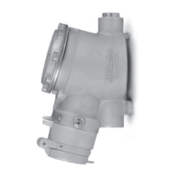
FSQC Series
Receptacle interlocked with switch for use in hazardous locations.
Compliance
UL Standards: 050E, 1010, 1203, 1682, 1686
CSA Standards: No.30, C22.2 No.25, C22.2 No.159
Electrical Ratings
Maximum Voltage: 600 V ac at 60 Hz
Current: 30 or 60 Amperes
Configuration: 3W, 4P
Applications
• Designed to supply power to portable or fixed electrical equipment such as motor generator units, welders, pumps,
compressors, and similar apparatuses.
• Ideal for use on shipping docks, ports, and other "Ship-to-Shore" applications.
• Suitable for use in locations where a weatherproof enclosure is required.
• Interlocked receptacle design provides use in hazardous locations and rough environments.
Features
• Rugged and Type 4X watertight enclosure and cover, sealed with an O-ring.
• Grounding Style—Style 2 receptacle ground through shell and extra pole.
Receptacle is dead front without plug engaged.
• Arcing Confined—Interlock receptacle design means that all electrical switching
is done with an internal switch. The plug cannot be engaged or disengaged with
the receptacle when the switch is ON.
• Positive Contact—Brass contacts have integral springs for positive, maintained,
electrical contact.
• Receptacle face enables the engagement of plugs for a weatherproof union.
• Positive Ground—Grounding terminal for Style 2 receptacle "makes first,
breaks last".
• Receptacle is designed so that it can only turn ON when the proper mating plug
is fully engaged and the padlocking collar is rotated. See Table 7 for a list of the
mating plugs.
• Receptacles come with both a flip cover and a screw cover for protection
against environmental conditions.
• Cover cannot be removed when the switch is ON.
• P4 Option—Special polarization prevents plug insertion into a receptacle wired
for a different voltage.
• Style 2 interlocked receptacles are equipped with contacts designed to provide
a safety polarization means called "controlled length" contacts. This feature will
not allow the plug grounding contact (Style 2) to touch an energized receptacle
"line" contact in the event the plug becomes damaged and/or loses its primary
polarization means and/or is rotated into the incorrect position.
Appleton • 1.800.621.1506 • www.appletonelec.com
303302 INSTRUCTION SHEET
TOP CONDUIT
FSQC 30
ENTRY
BOTTOM CONDUIT
SCREW
ENTRY & CLOSE-UP
COVER
PLUG
ASSEMBLY
FSQC 60
SCREW COVER
ASSEMBLY
303302 Rev. G 02/16 • Page 1 of 12
TOP CONDUIT
ENTRY
BOTTOM CONDUIT
ENTRY & CLOSE-UP
PLUG
Advertisement
Table of Contents

Related Manuals for Appleton FSQC 30 A

Summary of Contents for Appleton FSQC 30 A
- Page 1 “line” contact in the event the plug becomes damaged and/or loses its primary ENTRY & CLOSE-UP SCREW COVER PLUG polarization means and/or is rotated into the incorrect position. ASSEMBLY Appleton • 1.800.621.1506 • www.appletonelec.com 303302 Rev. G 02/16 • Page 1 of 12...
-
Page 2: Product Safety Information
WARNING—MODIFICATIONS Do not modify these devices in anyway. Replace any missing or broken parts with proper Appleton replacement parts. Modification of these devices or substitution of parts with non-standard parts may result in serious or fatal person injury from electrocution. - Page 3 16.30 CM 7.92 CM 2 CONDUIT ENTRIES (TOP & BOTTOM) SIZE 1-11 1/2 NPT OR 3/4-14 NPT WITH REDUCER Figure 2: FSQC 30 A Details & Parts List SWITCH TERMINAL SCREWS FOR LINE WIRE CONNECTIONS FACTORY WIRED Table 1: FSQC 30 A Parts List...
- Page 4 Switch actuating fork Ground lug wire Enclosure Switch actuator screws Screw Switch plate Switch mounting screws Screw cover assembly* Choose Item #1 or #18 based on the application. 303302 Rev. G 02/16 • Page 4 of 12 Appleton • 1.800.621.1506 • www.appletonelec.com...
-
Page 5: Installation
3. On all conduits, reducer bushings, and close-up plugs, grease must be used to completely seal out water. NOTE: We recommend applying Appleton thread lubricant (part number TLC-3) on threads in three generous lines, running parallel to the thread axis and spaced equidistant around the thread. -
Page 6: Electrical Testing
Close the Receptacle Cover 1. Apply a thin film of conductive grease (Appleton part number TLC-3 is recommended) on the threads of the housing. The purpose of this grease is to further ensure against water migration through the receptacle cover and housing joint. Grease should be reapplied each time the receptacle cover is opened. -
Page 7: Operation
ACP6034BC NOTES: • The Appleton FSQC receptacles and ACP plugs are UL Listed combinations. • Receptacles with the P4 option have the interior rotated 22 1/2 degrees for special polarization applications. They are compatible only with Appleton plugs with the P4 option. -
Page 8: Disconnect Switch
Figure 5: Receptacle Phase Designation—3 Wire, 4 Pole TERMINAL BLOCK LUG SCREW GROUNDING WIRE HALF MOON CONFIGURATION GROUNDING WIRE 303302 Rev. G 02/16 • Page 8 of 12 Appleton • 1.800.621.1506 • www.appletonelec.com... -
Page 9: Appendix A: Fsqc Receptacle Covers
• The Appleton FSQC receptacles and ACP plugs are UL Listed combinations. • The Appleton FSQC receptacle with Crouse-Hinds UL listed APJ series plugs are UL Classified combinations. • FSQC receptacle and APJ plugs are classified for Class I, Division 1, Groups B, C, and D. -
Page 10: Appendix C: Auxiliary Switch
Appleton Part Number Quantity per Assembly Mounting bracket 69303321000 Auxiliary switch 69303320000 Screw, 4-40 x 1/2" 69P05117000 Mounting screw, 10-24 x 3/8" 69P04639001 Quick disconnect terminal 69303339000 303302 Rev. G 02/16 • Page 10 of 12 Appleton • 1.800.621.1506 • www.appletonelec.com... - Page 11 1. The wiring must be checked and tested to ensure that all circuits are according to plan and that there are no unwanted opens, shorts, or grounds. 2. Turn the receptacle collar to the “ON” position. Appleton • 1.800.621.1506 • www.appletonelec.com 303302 Rev. G 02/16 • Page 11 of 12...
- Page 12 Appleton warranties DO NOT extend to, and no reseller is authorized to extend Appleton’s warranties to any consumer. While every precaution has been taken to ensure accuracy and completeness in this manual, Appleton Grp, LLC. assumes no responsibility, and disclaims all liability for damages resulting from use of this information or for any errors or omissions.
Need help?
Do you have a question about the FSQC 30 A and is the answer not in the manual?
Questions and answers