
Summary of Contents for Orlaco Loadview wireless
- Page 1 Tower crane Loadview wireless System manual Manual no. SM0974023 A 01 Set Art. No. 84060746 2018 English...
-
Page 2: Table Of Contents
Orlaco Products BV Service department. The camera and monitor systems from Orlaco comply with the latest CE, ADR, EMC and mirror-directive regulations. All products are manufac- tured in accordance with the ISO 9001 quality management, IATF 16949 quality automotive and ISO 14001 environmental management. -
Page 3: Introduction
System manual 1. Introduction With this Orlaco Loadview system the crane operator can see immediately on his monitor when a lifting operation could possibly become dangerous. The operator is no longer dependent on information from other persons by means of a portable radios. He can make the right decisions without delay and thus prevent accidents on site. -
Page 4: System Overview
System manual 3. System overview Tower crane cabin Tower crane trolley Battery set Art. No. 82023574 Quick-fit set Monitor 12” Serial Spectrum Scanner Camera AF Zoom Serial transmitter Art no 0103530 Coax core (Video) Coax screen (Video GND) AF-Zoom (+12V/DC) Camera Spectrum Scanner Black... -
Page 5: Battery Pack
W h e r y is b a tt e 100% Orlaco battery pack When LED is blinking battery is charging Figure 4 Cable Set Battery pack: Spider Cable Crane, Art. No. 84057405 3,85m, to Spectrum scanner... -
Page 6: Quick-Fit Set
System manual 6. Quick-fit set side view See figure 6 - Fit the AF-Zoom camera on the bracket of the Quick-fit set. - Fit the bracket of the Spectrum Scanner Transmitter on the ball joint of Quick-fit set Adjust the Quick-fit set. Camera - Check that the battery Set is stable and horizontal. -
Page 7: Spectrum Scanner Receiver
System manual 6.2. Mounting Quick-fit set to the tower crane trolley. bracket bracket with magnet foot with connection plate Mounting example: Top mounting 40.5 units in mm 20.3 Side mounting ∅7.0 ( 4x) 63.3 Top mounting 7. Spectrum Scanner receiver There are more possibilities to mount the Spectrum Scanner bracket on Top view the crane, see figure 8 and 13. - Page 8 7p male System manual 7p female 8p female 7.1. Connecting Spectrum Scanner receiver To Camera Connect the monitor cable to the 7p connection on the Spectrum Scanner Power input To Display receiver. See figure 9. (see specs) Receiver Solderside 7p connectors: 1 = Coax core (video) 5 = Orange (RX) PI 3)
-
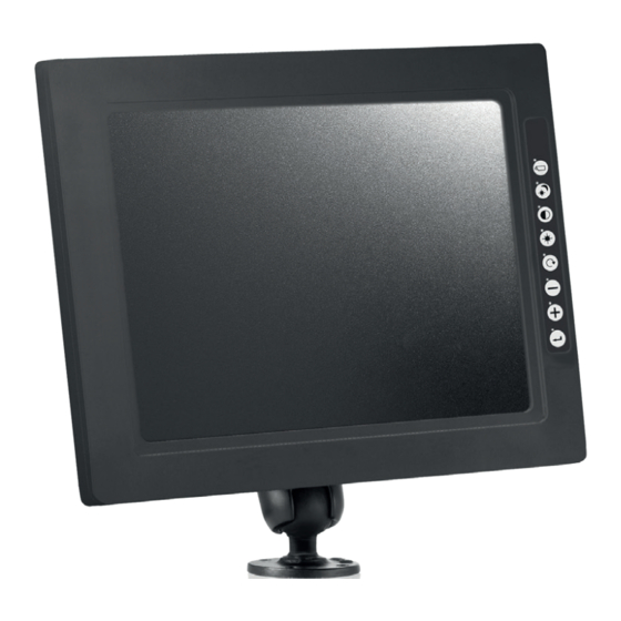
Page 9: Mounting The Monitor
System manual Connections to the monitor: (Secure the power input with a 5A fuse) 1 = Red = Power input: 18...30V 2 = White = Power input: 0V 3 = Blue = Cam No. 1 activated at 18...30V 8. Mounting the Monitor 4 = Brown = Cam No. -
Page 10: Mounting Foot Switch
System manual 9. Mounting Foot switch For zoom in and out, connect the Foot switch Art. No. 82023571 (Figure 13) to the Power supply, see system overview on page 4. Figure 13 10. Mounting overview At right you see the Spectrum Scanner Transmitter (Figure 14) mounted on a crane. -
Page 11: Disposal
BV. All rights reserved. No part of this manual may be reproduced and/ or made public in printed form, in photocopy form or on microfi lm, or in any other way, without the prior written permission of Orlaco. This also applies to the associated drawings and figures. - Page 12 ORLACO Orlaco is a production company specialised in making camera-, and monitor systems for commercial vehicles, fork-lift trucks, cranes, off shore and maritime. Our objective is to design and produce camera systems for the profes- sional market that improve the drivers view and increase operating efficiency.
Need help?
Do you have a question about the Loadview wireless and is the answer not in the manual?
Questions and answers