
Related Manuals for SystemAir X-RS485

Summary of Contents for SystemAir X-RS485
- Page 1 RS485 Gateway Wireless User Manual -en_GB Document in original language 2017-03-20 A005...
-
Page 2: Table Of Contents
Contents 1 Declaration of Conformity ....... 1 2 Product description ........3 3 Guidelines for installation ....... 4 4 Interface description ........5 4.1 Connections ........6 4.2 Power-up .......... 9 4.3 Active/User/Fault mode ......9 4.4 Binding mode ........11 5 Communication Interface Functions .... -
Page 3: Declaration Of Conformity
1 Declaration of Conformity Manufacturer Systemair AB Industrivägen 3 SE-739 30 Skinnskatteberg SWEDEN Office: +46 222 440 00 Fax: +46 222 440 99 www.systemair.com hereby confirms that SmartDial, CO2 sensor, Humidity sensor, Input module and RS485 Gateway comply with all applicable requirements in the Directive 2014/53/EU. - Page 4 The complete technical documentation is available. Skinnskatteberg, 20-03-2017 Mats Sándor Technical Director RS485 Gateway User Manual Systemair AB...
-
Page 5: Product Description
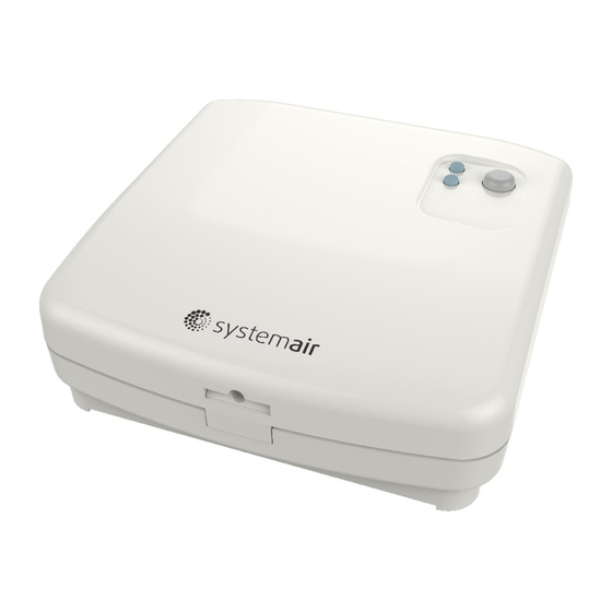
2 Product description The RS485 gateway is a wireless gateway between the Systemair air handling unit and wireless remote modules. The communication frequency is 868.3 MHz The wireless remote modules such as: SmartDial, Input Module, Humidity sensor and the CO sensor are all wirelessly connected to the RS485 gateway. -
Page 6: Guidelines For Installation
• All metallic parts in the building construction can weaken wireless signals. • Reinforced concrete walls and floors weaken the signal strength significantly, but almost all types of construction materials reduce the signal to some degree. RS485 Gateway User Manual Systemair AB... -
Page 7: Interface Description
Note: To get a good overview of the devices in each rooms, and their placement, Systemair recommends that an installation plan is made before beginning the actual installation. 4 Interface description The gateway is sending and receiving data wirelessly to the remote modules and is wired via an RS485 bus to the air handling unit . -
Page 8: Connections
1. Green and Red status LED’s. 2. Function button 4.1 Connections The Systemair air handling unit and the RS485 Gateway are interconnected by a cable: • Maximum cable length: 50 m. • Cable type: Flat 4–conductor CEC Phone cable, or equivalent. - Page 9 Function Screw/Ter- Coloured connection minal cable (#208263) 1 (A) RS485 A yellow 2 (G) GND (shielding) black RS485 Gateway User Manual Systemair AB...
- Page 10 Connect the cable to (3) on the air handling unit. If a control panel is already connected to (3), a diverting plug can be used to enable connection of both a gateway and the standard control panel. RS485 Gateway User Manual Systemair AB...
-
Page 11: Power-Up
After 2 seconds, the gateway will go to idle mode. In idle mode, the status LED’s are turned off. When the button is pushed the Active/User/Fault mode is entered. 4.3 Active/User/Fault mode In the Active/User/Fault mode, the LED’s can show the following status: RS485 Gateway User Manual Systemair AB... - Page 12 • If the button is released within these 3 seconds, the binding mode is entered. • If the button is not released within these 3 seconds, the LED goes off and the gateway will go to idle mode. RS485 Gateway User Manual Systemair AB...
-
Page 13: Binding Mode
5 minutes. The gateway will accept additional requests from remote modules without pressing the button again. If no bind request message is received for 5 minutes, the idle mode is entered. When the button is pressed again, the Active/User/Fault mode is entered. RS485 Gateway User Manual Systemair AB... -
Page 14: Communication Interface Functions
• If the button is released within these 5 seconds the reset operation is entered. • If the button is not released, the LED goes off and the gateway will go to idle mode. RS485 Gateway User Manual Systemair AB... -
Page 15: Troubleshooting
— Distance between gateway and remote modules too far. Max 30m. Revise placement of the equipment. — Metallic parts or other reflecting materials in the building construction. Revise placement of the equipment. RS485 Gateway User Manual Systemair AB... - Page 16 Systemair AB reserves the right to make changes and improvements to the contents of this manual without prior notice. Systemair AB Industrivägen 3 SE-739 30 Skinnskatteberg, Sweden Phone +46 222 440 00 Fax +46 222 440 99 www.systemair.com...
Need help?
Do you have a question about the X-RS485 and is the answer not in the manual?
Questions and answers