Table of Contents
Advertisement
Quick Links
Advertisement
Table of Contents

Subscribe to Our Youtube Channel
Related Manuals for BlazeVideo A280

Summary of Contents for BlazeVideo A280
- Page 1 Trail Camera Model#: A280 INSTRUCTION MANUAL V1.1...
-
Page 2: Table Of Contents
TABLE OF CONTENT 1. IN THE BOX............... 1 2. IMPORTANT NOTE...........1 3. INTRODUCTION............1 3.1. ABOUT THE CAMERA........1 3.2. MAIN FEATURES........... 2 3.3. APPLICATIONS..........3 4. PARTS AND CONTROLS......... 3 5. INSTALLING THE BATTERIES AND SD CARD.. 7 5.1. LOADING BATTERIES........7 5.2. -
Page 3: In The Box
SD card in the camera. 3. INTRODUCTION 3.1. ABOUT THE CAMERA The A280 trail camera is a new generation of digital scouting camera, it can be triggered by any movement of... -
Page 4: Main Features
game in a location, detected by a highly sensitive Passive Infra-Red (PIR) motion sensor, and then take high quality pictures (up to 24MP still photos), or 1296P H.264 video clips with audio. The camera features the all-new innovative and ultra-clear imaging technology, encompasses... -
Page 5: Applications
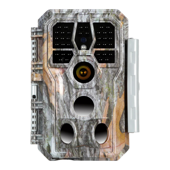
Operation Temperature: -4~140°F Support SD/SDHC/SDXC memory card, max capacity 256GB (user supplied) Extremely long in-field battery life up to 8 months in a stand-by state with 8 AA 1.5V batteries (user supplied) 3.3. APPLICATIONS The camera can be used as follows: For hunting and trailing animals’... - Page 6 IR LEDs Light Sensor Indicator Optical Lens Lock Hole Lens Lock Buckle Figure 1: Front View...
- Page 7 The camera provides the following connections for external devices: Mini USB port and SD card slot etc. (Figure 2). Tripod Base SD Card 1/4" - 20 Holder DC 12V/1A Microphone Plug 5.5x2.1mm Mini USB Port Figure 2: Bottom View The camera has one security cable hole and two strap holes on the back.
- Page 8 and operation, 8 AA batteries slot supported (Figure 4). Color Battery Screen Compartment and Cover Operation Buttons Figure 4: Inside View Surveillance Mode Power Switch Figure 5: Operation Buttons A power switch is used to power on (ON mode) or off the camera (OFF mode).
-
Page 9: Installing The Batteries And Sd Card
5. INSTALLING THE BATTERIES AND SD CARD Before you begin learning how to use your camera, you will first need to install a set of batteries and insert an SD card. Although that may only take you a minute, there are some important notes about both batteries and SD cards you should be aware of, so please take the time to read the following directions and cautions:... -
Page 10: Inserting The Sd Card
Figure 6: Loading the Batteries 5.2. INSERTING THE SD CARD Insert the SD card (with the camera powered off), before beginning to operate the camera. Don't insert or remove the 一 SD card when the camera is powered on or in the surveillance mode. -
Page 11: Using The Camera
card is not installed correctly, the device will not display an SD card icon on the screen in ON mode. Formatting the SD card by using the camera's "Format SD Card" menu option before first use is recommended, especially when a card has been used in other devices. To take out the SD card, just gently push in the card (do ... -
Page 12: The Off, On, And Surveillance Modes
7. THE OFF, ON, AND SURVEILLANCE MODES The camera has three basic operational modes: OFF mode: Power switch in the OFF position (The camera is powered off). ON mode: Power switch in the ON position (The camera is powered on and its screen is on). SURVEILLANCE mode: When the camera is powered ... -
Page 13: Surveillance Mode
screen that shows how many images have been taken, the battery level, camera or video mode, etc. Attention please: In the ON mode, the camera will automatically enter SURVEILLANCE mode if there is no operation (key pressing) within 5 minutes. Then the camera will perform as your settings in the menu. - Page 14 enter/exit the menu. Press the UP/DOWN key to move the marker, Press the LEFT/RIGHT key to change the setting, and press the OK key to confirm the change. Always remember to press the OK to save the change. Otherwise you will lose your new setting. Settings Parameter Description...
- Page 15 keeps 30 seconds. Video Selecting On will record video with sound. Sound MP4 is the mainstream format in the video industry, more compatible with any player. Video Select MOV in case some legacy digital Format camera software must be working with videos in MOV format.
- Page 16 any of the two side motion sensors detects a motion event, the camera will be pre-activated. If the animal enters the detection area of the center motion sensor within 5 seconds, the camera will take photos or videos per your settings, otherwise the camera will re-enter standby mode again.
- Page 17 Select On to assign a 4-character long in the form of Capital A-Z, 0-9 to record the Camera location in the photos (e.g. A123 for Yellow Name Stone Park). This helps multi-camera users identify the location when reviewing the photos. Select On to show date, time, temperature, Info Strip moon phase on each capture.
-
Page 18: Mounting And Positioning
Version Defined Display the version of the camera. 9. MOUNTING AND POSITIONING 9.1. MOUNTING After you've set up the camera's parameters to your personal preferences at home, you're ready to take it outside and the camera is in the SURVEILLANCE mode. When setting up the camera for scouting game or other outdoor applications, you must be sure to mount it in place correctly and securely. -
Page 19: Sensing Angle And Distance Test
Figure 8: Mounting the Camera 9.2. SENSING ANGLE AND DISTANCE TEST To test whether the camera can effectively monitor the area you choose, this test is recommended to check the sensing angle and monitoring distance of the camera. To perform the test: Switch the camera to the ON mode. -
Page 20: Starting
is outside of the sensing area. In these sensing test, the camera would take pictures once motion captured. When you open the camera, the screen shows the number of times triggered, you can review the pictures on the screen. (Note: The red light will blink only when the motion is within the sensing area of the central PIR sensor. -
Page 21: Review Photos Or Videos
delay, and then ready to capture, go into surveillance mode. Any motion that is detected by it will trigger the capture of images as programmed in the menu. Be sure you have read the descriptions of the Detection Delay, PIR Sensitivity parameters. -
Page 22: Technical Specifications
11. TECHNICAL SPECIFICATIONS Element Description Working Mode Motion detection or Time Lapse Max. Pixel Size 24MP Lens F=1.6, FOV=70°, Auto IR-Cut IR Flash 100ft LCD Screen 2.4" Color screen Keypad 7 Keys, 1 Power switch SD, SDHC or SDXC Regular memory card Memory (Not included), max capacity 256GB Picture... -
Page 23: Troubleshooting
Operation On /Off, Specific working period of time Hours Password 4-Digit Code Camera Name 4-Character (A-Z, 0-9) Time Lapse 2 Seconds ~ 24 Hours Interval Power Supply 8x1.5V AA Batteries (Not included) Stand-by Time 8 Months Auto Stand-by (Surveillance mode) in 5 minutes Auto Stand-by while no operation in the ON mode 8V - Low Battery (Batteries die) - Page 24 check: Make sure the camera is powered on and in the right mode Format the SD card in the camera or replace the SD card since the SD card is a storage media and sometimes it might be unstable Replace batteries if night vision seems not working as expected ...
-
Page 25: Warranty
13. WARRANTY ONE YEAR LIMITED WARRANTY Your Trail Camera warranty covers your trail camera for one year after the original purchase date. We warrant that your camera will be free from defects in materials and workmanship when operated in normal use and conditions. This warranty does not cover consumer caused damages such as misuse, abuse, improper handling or installation, damaged caused by wild animals, or repairs attempted by someone other than our... -
Page 26: Fcc Compliance Statement
14. FCC COMPLIANCE STATEMENT This equipment has been tested and found to comply with the limits for a Class B digital device, pursuant to part 15 of the FCC Rules. These limits are designed to provide reasonable protection against harmful interference in a residential installation. Operation is subject to the following two conditions: (1) This device may not cause harmful interference, and (2) this device must accept any interference received, including interference that may cause...
Need help?
Do you have a question about the A280 and is the answer not in the manual?
Questions and answers