Table of Contents
Advertisement
Quick Links
SERVICE
PERSONAL MICRO COMPONENT SYSTEM
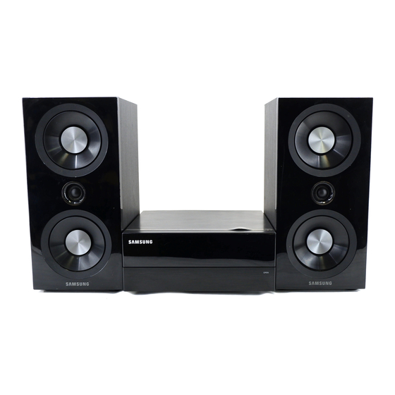
MM-D530D
Refer to the service manual in the GSPN (see the rear cover) for the more information.
PERSONAL MICRO
COMPONENT SYSTEM
Model Name : MM-D530D
Model Code : MM-D530D/RU
Manual
1. Precaution
2. Product Specification
3. Disassembly & Reassembly
4. Troubleshooting
5. PCB Diagram
6. Schematic Diagram
CONTENTS
Advertisement
Table of Contents

Related Manuals for Samsung MM-D530D


Summary of Contents for Samsung MM-D530D
- Page 1 PERSONAL MICRO COMPONENT SYSTEM Model Name : MM-D530D Model Code : MM-D530D/RU SERVICE Manual PERSONAL MICRO COMPONENT SYSTEM CONTENTS 1. Precaution 2. Product Specification 3. Disassembly & Reassembly 4. Troubleshooting 5. PCB Diagram 6. Schematic Diagram MM-D530D Refer to the service manual in the GSPN (see the rear cover) for the more information.
- Page 2 E.Asia, W.Asia, https://gspn2.samsungcsportal.com China, Japan N.America, https://gspn3.samsungcsportal.com S.America © Samsung Electronics Co.,Ltd. Apr. 2011 This Service Manual is a property of Samsung Electronics Printed in Korea Co.,Ltd. Any unauthorized use of Manual can be punished under applicable International and/or domestic law.
-
Page 3: Table Of Contents
Contents 1. Precaution 1-1 Safety Precautions ................... 1-1 1-2 Servicing Precautions ..................1-3 1-3 Precautions for Electrostatically Sensitive Devices (ESDs) ......1-4 2. Product Specification 2-1 Product Feature ....................2-1 2-2 Specifications ....................2-2 2-3 Specifications Analysis ..................2-4 2-4 Accessories ......................2-5 3. Disassembly & Reassembly 3-1 Overall Disassembly &... -
Page 4: Precaution
1 and 5.2 megohms. If there is no return path, the measured resistance should be “infinite.” If the resistance is outside these limits, a shock hazard might exist. See Fig. 1-2 Samsung Electronics... - Page 5 . Use replacement components that have the same ratings, especially for flame resistance and dielectric strength specifications. A replacement part that does not have the same safety characteristics as the original might create shock, fire or other hazards. Samsung Electronics...
-
Page 6: Servicing Precautions
8. Always connect a test instrument’s ground lead to the instrument chassis ground before connecting the positive lead; always remove the instrument’s ground lead last. First read the “Safety Precautions” section of this manual. If some unforeseen circumstance creates a conflict between the servicing and safety precautions, always follow the safety precautions. Samsung Electronics... -
Page 7: Precautions For Electrostatically Sensitive Devices (Esds)
8. Minimize body motions when handling unpackaged replacement ESDs. Motions such as brushing clothes together, or lifting a foot from a carpeted floor can generate enough static electricity to damage an ESD. Samsung Electronics... -
Page 8: Product Specification
2 CH • Powerful Sound Experience 120W Powerr USB Host w/ video playback Tuner iPod (Option) DAB (Option) Various Multimedia Playback • MP3, WMA 2-1-2 MM-D530D Product Feature 2 CH • Powerful Sound Experience 160W Power DVD Disc USB Host w/ video playback Tuner iPod (Option) DAB (Option) -
Page 9: Specifications
Diameter: 120 or 80 mm. Thickness: 1.2 mm 60W/CH X2 RMS,IEC (total harmonic distortion: 10 %) Front Speaker (8Ω) (MM-D430, MM-D430D) AMPLIFLER Channel separation 60 dB Signal/noise ratio 70 dB Power Consumption GENERAL Dimensions 230 (D) x 98 (H) x 240 (W) mm Weight 1.9 Kg Samsung Electronics... - Page 10 Product Specification 2-2-2 MM-D530D Specifications Basic Specification Signal/noise ratio 55 dB Usable sensitivity 12 dB RADIO FM Total harmonic 0.5 % distortion Capacity 1 discs Frequency range 20 Hz - 20 KHz (± 1 dB) COMPACT Signal/noise ratio 90 dB (at 1 KHz) with filter DISC Distortion 0.05 % (at 1 KHz)
-
Page 11: Specifications Analysis
Product Specification 2-3 Specifications Analysis MM-DG35 Model Name MM-D430 / MM-D430D MM-D530D Photo 2CH 160W Output Power 2CH 120W 2CH 160W Front Display Touch Key Switch Touch Touch CD/DVD TAPE USB HOST CD RIPPING DNSe EQ/DSP DNSe DNSe Aux In ... -
Page 12: Accessories
Product Specification 2-4 Accessories 2-4-1 Supplied Accessories Accessories Item Item code Remark AH59-02146H Remote Control AH96-00051A iPod Dock 4301-000116 Battery Samsung Service Center AH39-40001V Audio Cable AH42-00021A FM Antenna AH68-02344P User's Manual Samsung Electronics... - Page 13 MEMO Samsung Electronics...
-
Page 14: Disassembly & Reassembly
- Be sure to carefully read and understand the safety instructions before performing any work as the IC chips on the PCB are vulnerable to static electricity. - Assemble in the reverse order of disassembly. Description Description Photo 1) Unfasten 1(8EA) screws on the CABINET-SIDE back. Samsung Electronics... - Page 15 Disassembly & Reassembly Description Description Photo 1) Unfasten 3(2EA+1EA) screws on the CABINET-TOP side and middle. 1) Unfasten 7 screws. 1) Unfasten 1 screw. Samsung Electronics...
- Page 16 Disassembly & Reassembly Description Description Photo 1) Turn over the hook of CABINET-BOTTOM and separate ASSY-FRONT Unfasten 2(1EA*2) screws. Samsung Electronics...
- Page 17 Disassembly & Reassembly Description Description Photo 1) Turn off the Spring-Door. 1) Unfasten 4 screws on the MAIN-PCB. 1) Unfasten 3 screws on the DECK-MECHA. Samsung Electronics...
- Page 18 Disassembly & Reassembly Description Description Photo 1) Unfasten 2 screws on the MPEG-PCB. 1) BOTTOM Samsung Electronics...
- Page 19 MEMO Samsung Electronics...
-
Page 20: Troubleshooting
2. Check pattern or replace them 3. Check SMPS part (high voltage, danger). Check or replace signal line, Check IC21 Pin 8 X-TAL (Micom Reset), X-TAL2, X-TAL3 Refer to wave pattern image of Fig. 4-2. Replace MICOM IC Samsung Electronics... - Page 21 Troubleshooting IC15 MAIN, page 7-4 IC814 IC21 MAIN PCB Top, page 6-2 <Fig. 4-1> Samsung Electronics...
- Page 22 Troubleshooting IC15 MAIN, page 7-4 IC814 IC21 MAIN PCB Top, page 6-2 <Fig. 4-2> Samsung Electronics IC1P104...
- Page 23 Check MAIN PCB IC9 Pin 19 Pin 44: Low Normal, High Mute : Low Mute; High Normal Refer to wave pattern image of Fig. 4-3. Check MAIN PCB Check power pattern L1S31: +24V, L1S30: -24V Replace IC9 Samsung Electronics...
- Page 24 Troubleshooting IC17 MAIN, page 7-4 MAIN PCB Top, page 6-2 <Fig. 4-3> PCW1 Samsung Electronics...
-
Page 25: Measures To Be Taken When The Protection Circuit Operates
(Caution!: Do not connect the power cord during bellow test!) Measurement Resistance using Tester - Approximately - MM-D430D/D530D L/R CH 1 kΩ <Table 4-1> If Measured Resistance is very different from above numbers, There is a Problem. → AMP PART Problem Samsung Electronics... -
Page 26: Micom, Mpeg Initialization & Update
2. Insert USB Memory, and play. “Updating” will be displayed. Set will be power off → on. 3. The disc is automatically ejected. (If you use USB memory, detach USB memory.) DVD flash initialize 1. During “No Disc” displayed, push the stop button 5 seconds. After displayed “INITIALIZE” power off. 2. Finished. Samsung Electronics... -
Page 27: Buyer-Region Code Setting Method
Insert number “3”, “3” to select Region Code. TEST − − 4. After step (3), you can see “− −” on the VFD. Insert the Region Code corresponding model with − − “0 ~ 9” buttons on the remote control. 5. Turn the Power off. Samsung Electronics... - Page 28 Troubleshooting Option Table-1 Area MM-D430D Region Code Remark Africa, Pakistan BRAZIL CANADA China(semi_mic) Europe Indonesia,HONGKONG JAPAN Latin American Mexico Philippines Russia(full_mic) Russia(semi_mic) South Africa Taiwan Newzealand England Australia Iran(HACO) India Israel Middle Asia Asia Singapore THAILAND MOROCCO <Table 4-2> Samsung Electronics...
- Page 29 Troubleshooting Option Table-2 Area MM-D530D Region Code Remark Africa, Pakistan BRAZIL CANADA China(semi_mic) Europe Indonesia,HONGKONG JAPAN Latin American Mexico Philippines Russia(full_mic) Russia(semi_mic) South Africa Taiwan Newzealand England Australia Iran(HACO) India Israel Middle Asia Asia Singapore THAILAND MOROCCO <Table 4-3> 4-10 Samsung Electronics...
-
Page 30: Pcb Diagram
PCB Diagram 5. PCB Diagram 5-1 Wiring Diagram Samsung Electronics... -
Page 31: Main Pcb Top
PCB Diagram 5-2 MAIN PCB Top IPCON1 IPIC1 1SIC01 2SIC01 MIC1 MIC2 MIC5 MIC3 IC15 IC16 IC17 HIC31 KIC1 IC21 IC814 IC522 IC1P104 DCON10 PCW1 CON5 Samsung Electronics... - Page 32 CL_M B_CLK CL_M OP_M HDMI_5.6V OP_M V_ON LD_CHK TV_SW LD_CHK V_UP U_RXD LINE_L U_RXD LED1 U_STB SGND U_STB LED2 U_TXD LINE_R U_TXD LED3 U_ACK iPod_DET U_ACK LED4 U_RST AN_RCH U_RST LED5 CEC_TXD iPod_VSW CEC_TXD LED6 CEC_RXD AN_LCH CEC_RXD Samsung Electronics...
- Page 33 9 MCON2 DECK Data MPEG Power/Signal Connector Pin No. Signal Pin No. Signal CD-VR USB5V USB5V CD-LD USB5V LD-GND DGND DGND D3.3V D3.3V MCLK TSD0 LRCLK B_CLK HDMI_5.6V Vref TV_SW LINE_L DVD-VR SGND LINE_R DVD-LD iPod_DET RFCON1 AN_RCH H-Vcc iPod_VSW AN_LCH Samsung Electronics...
-
Page 34: Main Pcb Bottom
PCB Diagram 5-3 MAIN PCB Bottom 1SIC01 2SIC01 DCON10 PCW1 CON5 Samsung Electronics... -
Page 35: Key Pcb Top
PCB Diagram 5-4 KEY PCB Top KEYCN1 TIC1 KEYIC2 Samsung Electronics... -
Page 36: Key Pcb Bottom
PCB Diagram 5-5 KEY PCB Bottom Samsung Electronics... - Page 37 MEMO Samsung Electronics...
-
Page 38: Schematic Diagram
#3, 6, 9, 12 Function IC R2S15904 #42 AMP Mute MUTE EQ/3D DG36 #36, 37, 38, 39 3.0 CH option 100W/CH L/R Audio Headphone iPod L/R Audio Headphone OP AMP Analog Samsung Electronics This Document can not be used without Samsung’s authorization. -
Page 39: Front
Schematic Diagram 6-2 FRONT This Document can not be used without Samsung’s authorization. Samsung Electronics... -
Page 40: Touch Key
0OHM LED4 LED3 SS501 KEY_SCL KEYIC2 1/10W 0OHM LED2 KEYR11 KEY-SDA 0.05OHM 1/10W 2.2KOHM LED1 KEYR9 POWER ST5V 100NF 100NF ASES12U030R2 BIAS SENS 100NF 1/10W POWERKEY 10KOHM GND-1 KEYCN1 Samsung Electronics This Document can not be used without Samsung’s authorization. -
Page 41: Main
Schematic Diagram 6-4 MAIN POWER AUDIO This Document can not be used without Samsung’s authorization. Samsung Electronics... -
Page 42: Mpeg
Schematic Diagram 6-5 MPEG POWER AUDIO VIDEO Samsung Electronics This Document can not be used without Samsung’s authorization. -
Page 43: Smps
Schematic Diagram 6-6 SMPS POWER This Document can not be used without Samsung’s authorization. Samsung Electronics...
Need help?
Do you have a question about the MM-D530D and is the answer not in the manual?
Questions and answers