Table of Contents

Related Manuals for Niveo Professional NUPS23 Series

Summary of Contents for Niveo Professional NUPS23 Series
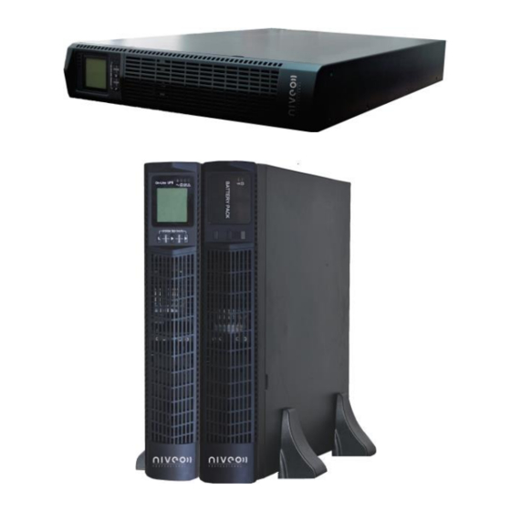
- Page 1 Manual NUPS23 Series Niveo Professional True Sine Wave Double-Conversion Online Rack/Tower UPS NUPS23-1000- 1.0KVA/900W NUPS23-2000-2.0KVA/1800W NUPS23-3000- 1.0KVA/2700W More information: WWW.NIVEOPROFESSIONAL.COM INFO@NIVEOPROFESSIONAL.COM...
-
Page 2: Table Of Contents
Table of Contents Important Safety Warning ......................2 Transportation ........................2 Preparation ........................2 Installation ......................... 2 Operation ........................... 3 Maintenance, service and faults ..................3 Symbols used in this guide ..................... 4 Installation and setup ........................4 Unpack checking ....................... 4 Real panel view ......................... -
Page 3: Important Safety Warning
1. Important Safety Warning Important safety instructions – Save these instructions Please comply with all warnings and operating instructions in this manual strictly. Save this manual properly and read carefully the following instructions before installing the unit. Do not operate this unit before reading through all safety information and operating instructions carefully There exists dangerous voltage and high temperature inside the UPS. -
Page 4: Operation
1-4 Operation Do not disconnect the mains cable on the UPS system or the building wiring outlet (shockproof socket outlet) during operations since this would cancel the protective earthing of the UPS system and of all connected loads. The UPS system features its own, internal current source (batteries). The UPS output sockets or output terminals block may be electrically live even if the UPS system is not connected to the building wiring outlet. -
Page 5: Symbols Used In This Guide
1-6 Symbols used in this guide WARNING! Riskofelectricshock CAUTION! Readthisinformationtoavoidequipmentdamage 2. Installationand setup NOTE: Before installation, please inspect the unit. Be sure that nothing inside the package is damaged. Please keep the original package in a safe place for future use. 2-1 Unpack checking ... - Page 6 2KVA(S): 2KVA(H)/3KVA(H) 3KVA(S):...
-
Page 7: Lcd Control Panel
AC input Network /Fax/Modem Surge Protection(option) Input circuit breaker EPO(option) USB communication port(option) RS-232 communication port SNMP intelligent slot (option) Output receptacles Battery Terminal 10. Output Terminal 2-3 LCD control panel LCD control panel introduction (1)LED(from top to bottom: “alarm”, “bypass”, “battery”, “inverter”) (2)LCD display(3) Selectbutton:enter to next item(4)Off button (5)On button 2-4 Setup the UPS Step 1: UPS input connection... - Page 8 package. Step 2: UPS output connection For socket-type outputs, simply connect devices to the outlets. For terminal-type input or outputs, please follow below steps for the wiring configuration: a) Remove the small cover of the terminal block b) Suggest using AWG14 2.1mm...
-
Page 9: Operations
3. Operations 3-1 Button operation Function Button Turn on the UPS: Press and hold ON button for at least 2 seconds to turn on the UPS. Down key: Press this button to display next selection in ON Button UPS setting mode. -
Page 10: Lcd Display
3-2 LCD display There are 8 interfaces available in the LCD display Item Interface Description Content Displayed Input voltage Battery voltage Output voltage... - Page 11 Load Temperature (Environment Temperature & Heatsink Temperature) Firmware Version & UPS model.
-
Page 12: Ups Setting
CODE (Operational status and mode) Alarm Code(Warming Message) All alarm codes are present when abnormal behavior(s) occur(s) The charging status can also be shown on the screen as below while the charger is on. 3-3 UPS setting The setting fuction is controled by 3 buttons (Enter/Select,Off/up ▲, On/down▼): Enter +Off/up ▲---goes into the setting page,Enter --- value adjustment;... - Page 13 Item Settings Content Displayed Mode setting Press select button to change the setting (ECO or NOR). Press UP button ▲ to select the previous setting. Press DOWN ▼ button to select the next setting. Output voltage setting Press select button to change the setting (100,110,115,120,127 200,208,220, 230, 240).
- Page 14 Bypass voltage upper limit setting Press select button to change the setting(The bypass voltage upper limit range is 230-264Vac ). Press UP button ▲ to select the previous setting. Press DOWN ▼ button to select the next setting. Bypass voltage lower limit...
-
Page 15: Operating Mode Description
3-4 Operating Mode Description Operating mode Description Display When the input voltage is Online mode Inverter led light within acceptable range, UPS will provide pure and stable AC power to output. The UPS will also charge the battery at online mode. Energy saving mode: ECO mode Bypass led light... -
Page 16: Alarm Or Fault Reference Code
3-6 Alarm or Fault reference code Event log UPS Alarm Warning Buzzer Rectifier Fault Beep continuously Fault LED lit Inverter fault(Including Inverter Beep continuously Fault LED lit bridge is shorted) Fan fault Beep continuously Fault LED lit Selftest fault Beep continuously Fault LED lit Battery Charger fault Beep continuously... -
Page 17: Troubleshooting
4. Troubleshooting If the UPS system does not operate correctly, please solve the problem by using the table below. Symptom Possible cause Remedy Check if input power cord The AC input power is not firmly connected to the No indication and alarm connected well. -
Page 18: Storage And Maintenance
5. Storage and Maintenance Operation The UPS system contains no user-serviceable parts. If the battery service life (3~5 years at 25°C ambient temperature) has been exceeded, the batteries must be replaced. In this case, please contact your dealer. Be sure to deliver the spent battery to a recycling facility or ship it to your dealer in the replacement battery packing material. -
Page 19: Specification
6. Specification 1KVA(H)- 2KVA(H)- 3KVA(H)- MODEL 1KVA(S) 1KVA(H) 2KVA(S) 2KVA(H) 3KVA(S) 3KVA(H) PHASE Single phase with ground Capacity (VA/Watts) 1000VA / 900W 2000VA / 1800W 3000VA / 2700W INPUT Nominal voltage 200/208/220/230/240VAC 160Vac±5% @100%-80% load; 140Vac±5% @80%-70% load; line 120Vac±5% @70%-60% load; transf 110Vac±5% @60%-0% load;... - Page 20 depends on the depends on the depends on the 12V9A capacity of 12V9A capacity of Battery Type capacity of external 12V9AH external external batteries batteries batteries Numbers Backup time Long run unit depends on the capacity of external batteries Typical recharge 4 hours recover to 90% capacity (Typical) time(standard modle) 27.4...