
Related Manuals for BM2 BIEMMEDUE BMP 26 C

Summary of Contents for BM2 BIEMMEDUE BMP 26 C
- Page 1 Gas fired room sealed unit heaters centrifugal TECHNICAL INFORMATION, ASSEMBLY INSTRUCTIONS, USE AND MAINTENANCE BMP C BMP CS BMP C-2 BMP C-2S...
-
Page 2: Compliance Notices
UP RATED FAN Type Model Model Model Model BMP 26 C BMP 26 CS BMP 26 C -2 BMP 26 C -2S BMP 36 C BMP 36 CS BMP 36 C -2 BMP 36 C -2S BMP 46 C BMP 46 CS... - Page 3 INDEX GENERAL Description of equipment page. Identification “ Description “ Technical data “ Wiring diagram “ Remote control connections “ FOR THE USER Operation “ Servicing “ Heater indication lights “ Receipt of product and transport “ Dimension and weight “...
-
Page 4: General Notes
GENERAL NOTES This Instruction Manual is an integral part of the device All heaters must be fitted exclusively with original and as such must always be kept with the device. This accessories. The Manufacturer is not responsible also when the heater is sold to another user. The for any damage caused by improper use of the Manual must therefore be conserved carefully and heater and by the use of accessories that are not... - Page 5 GENERAL NOTES The use of devices that employ electrical energy and/or fuel oil requires the observance of some fundamental safety rules such as: Children ad unassisted disabled persons must not use Do not open any doors that access the inside of the the warm air heaters.
-
Page 6: Description Of Equipment
DESCRIPTION OF EQUIPMENT Heat exchanger Control and safety thermostat • The heater is controlled by three thermostats pre set to the Stainless steel construction easily accessible for following. inspection and cleaning and maintenance operations. • Patented exchange elements made in stainless steel LM Limit thermostat (100°C) modular sections with large surface area, trapezoidal in Capillary type. - Page 7 IDENTIFICATION If the TECHNICAL DATA is lost or damaged ask Manufacturer Technical Department duplicate. Check code and model is as data plate. Position of data plate Manufacturer AIR HEATER Model Serial Number Country Category Code Type Year Nominal Heat INPUT Nominal Heat OUTPUT Air Flow (+15°C) Electrical Supply...
- Page 8 DESCRIPTION Type 1÷4 NOTE: Heaters type 1, 2, 3 have a single burner manifold. Heaters type 4 have two burner manifolds 1. Regulation thermostat SND 19. Red light lockout indication 2. FAN thermostat TR 20. Lockout reset 3. LIMIT thermostat LM 21.
- Page 9 Type 5 and 6: NOTE: Heaters type 5 are supplied with 2 opposing burner manifolds Heaters type 6 are supplied with 4 opposing burner manifolds 1. Regulation thermostat 20. Yellow limit indication light 2. LIMIT thermostat 21. Red light lockout indication 3.
-
Page 10: Technical Data
TECHNICAL DATA DESCRIPTION TYPE UNIT HEAT OUTPUT 25,4 33,8 46,3 65,0 85,0 104,7 21.844 29.068 39.818 55.900 73.100 90.042 kcal/h HEAT INPUT 23,0 30,5 41,7 58,6 76,6 94,3 (Nett) 19.780 26.230 35.862 50.396 65.876 81.098 kcal/h EFFICIENCY 90,1 90,2 90,1 90,1 90,1 90,1... -
Page 11: Wiring Diagram
WIRING DIAGRAM Schematic layout: Heaters type 1-2-3 I° II° RSTR IGN1 KEY: Temperature control probe Ignition electrode Regulatory control thermostat(auto reset) Ionisation probe LIMIT thermostat (manual reset) Control board EVG1-I° Gas solenoid valve IMT (*) Fused isolator EVG1-II° Gas solenoid min (two stage) MS (*) Fire switch Capacitor / centrifual fan... - Page 12 Heater type 2-3 up rated fan I° II° RSTR IGN1 Electrical supply single phase 230V 50Hz KEY: Temperature control probe Ionisation probe Regulatory control thermostat(auto reset) Control panel LIMIT thermostat (manual reset) Relay fan motor EVG1-I° Gas solenoid valve Fan contactor EVG1-II°...
- Page 13 Heater type 4 I° II° RSTR IGN1 Electrical supply threephase 400V 50Hz 3N KEY: Temperature control probe Ionisation probe Regulatory control thermostat(auto reset) Control panel LIMIT thermostat (manual reset) Relay fan motor EVG1-I° Gas solenoid valve Contactor fan motor EVG1-II° Gas solenoid min (two stage) Line fuse Capacitor / centrifual fan IMT (*)
- Page 14 Heaters type 5-6 I° II° RSTR IGN1 IGN2 Electrical supply threephase 400V 50Hz 3N KEY: Temperature control probe Ignition electrode 1 Regulatory control thermostat(auto reset) Ignition electrode 2 LIMIT thermostat(manual reset) Ionisation probe EVG1-I° Gas solenoid valve 1 Control panel EVG2-I°...
-
Page 15: Remote Control Connections
REMOTE CONTROL CONNECTIONS Remote switchboard with thermostat (Optional) connection scheme VERSION SINGLE STAGE VERSION TWO STAGE DESCTIPTION: Multifunction electronic plate READ THE INSTRUCTION MANUAL BEFORE Remote control switchboard PROCEEDING WITH THE INSTALLATION. MS (*) Fire dumper’s switch (if necessary) THIS HEATER IS NEUTRALLY SWITCHED (*) Not included in the apparatus, to be supplies and ENSURE THAT THE WIRING IS CORRECT assembled by the Customer. - Page 16 Remote switchboard with thermostat and timer (Optional) connection scheme VERSION SINGLE STAGE VERSIONE BISTADIO DESCTIPTION: Multifunction electronic plate READ THE INSTRUCTION MANUAL BEFORE Remote control switchboard PROCEEDING WITH THE INSTALLATION. MS (*) Fire dumper’s switch (if necessary) THIS HEATER IS NEUTRALLY SWITCHED (*) Not included in the apparatus, to be supplies and ENSURE THAT THE WIRING IS CORRECT TO assembled by the Customer.
-
Page 17: Operation
OPERATION To switch ON the heater To switch OFF fan • • Switch the fused isolator switch ON (supply Set ON/STANDBY switch to STANDBY customer) • Stop Switch the heater ON/OFF selector to “ON” • Turn the selector switch to STOP •... -
Page 18: Heater Indicator Lights
HEATER INDICATOR LIGHTS If a fault should occur with the heater the lights situated at the right hand side of the heater will be illuminated indicating the fault • Red Lockout indication (1). This will be illuminated if the heater has gone to lockout due to the loss of flame sensing by the flame probe situated in the burner assembly in order to reset the heater the RESET Button (2) should be pressed (if... - Page 19 DIMENSION AND WEIGHT Type 1 – 2 – 3 – 4 Type A [mm] 1170 B [mm] C [mm] D [mm] E [mm] F [mm] G [mm] H [mm] 1216 J [mm] K [mm] L [mm] 1225 1225 1225 1273 ∅1 [mm] ∅2 [mm] ∅...
- Page 20 Type – 5 – 6 Type A [mm] 1720 1960 C [mm] 1300 1540 H [mm] 1644 1885 J [mm] 1200 1440 ∅ [inch] ¾ ¾ Nett weight [kg] male male...
-
Page 21: Installation
INSTALLATION It is a requirement that only qualified and competent Where the passage of cold air causes problems (eg by personnel may undertake installation commissioning entrances, loading bays etc) it is considered favourable and servicing of Heaters. if the heater is positioned so as the discharge towards or across the cold air source from a distance from 1.5m - 6m dependent upon the size of the entrance and the WARNING... -
Page 22: Installation Clearances
INSTALLATION CLEARANCES For the correct operation of heater and for maintenance purposes the following minimum clearances around the heater should be observed min. 700 Minimum200 mm type1 – 2 – 3 – 4 ✴ Minimum 700 mm type 5 – 6 Heater with warm air duct air inlet from below heater only min. -
Page 23: Examples Of Installation
EXAMPLES OF INSTALLATION Further examples INSTALLATION: • Internal installation • Mounted on wall brackets (1) • Ducted warm air outlet (2) • Open return air or ducted (3) from inside the building • Filter (4) Air Inlet casing (5) Type 1÷3 4÷6 1635... - Page 24 ACCESSORIES Available accessories: DESCRIPTION TYPE Conical duct connection Horizontal louvres Fire damper Air discharge damper Air inlet damper Air filter Rain proof inlet cowl Damper motor Manual control for damper Control arm Wall bracket Support beam Remote controller...
-
Page 25: Gas Connection
GAS CONNECTION Connection of the heater to the gas supply, whether • The gas supply and meter are capable of delivering Natural Gas or L P G , must be carried out in the required volume of gas to ensure the correct compliance with the installation laws and by burner pressure can be achieved See TECHNICAL qualified personnel. -
Page 26: Flue And Combustion Options
FLUE AND COMBUSTION OPTIONS Room sealed unit heaters are suitable for installation with the following flue configurations : B Option B • In this configuration the heater is connected to a single All joints should be sealed flue pipe to discharge the products of combustion •... - Page 27 : Single pipe flue to outside wall or roof terminal. Combustion air from inside building MIN. 400 MAX 500 Ø100 MIN 400 INSTALLATION DISTANCES FOR FLUE PIPE: HORIZONTAL FLUE VERTICAL FLUE TYPE UNIT L1 MIN. L1 MAX. L2 MIN. L2 MAX. 1,00 5,00 1,00...
- Page 28 : Horizontal flue installation twin pipe and concentric flue terminals. MIN. 400 ✴ 100 mm type 1 – 2 – 3 150 mm type 4 – 5 – 6 MAX 500 MIN. 400 MAX 300 INSTALLATION DISTANCES FOR FLUE PIPE: TWIN PIPE SYSTEW HORIZONTAL CONCENTRIC TERMINAL TYPE...
- Page 29 Concentric vertical roof terminal Ø150 Ø100 ✴ 100 mmtype 1 – 2 – 3 150 mm type 4 – 5 – 6 INSTALLATION DISTANCES FOR FLUE PIPES: VERTICAL ROOF TERMINAL TYPE UNIT L1 MIN. L1 MAX. 10,00 10,00 10,00 10,00 10,00 10,00 •...
-
Page 30: Electrical Connection
ELECTRICAL PANEL AND CIRCUIT BOARD Panel illustrated is fitted to type 5 and 6. Lockout reset Control box cover Red lockout indication light Differential pressure switch Yellow temperature indication light 10. Main fuse (type 4-5-6, 2-3 up rated fan) Green operating light 11. -
Page 31: Duct Connection
The cover to the electrical panel can be removed by ancillary electrical items e.g. room undoing the screws which secure it to the panel. A copy thermostats, time switches, remote panels etc, of the wiring diagram is affixed to the inside of the must be wired into the heater electrical circuit in cover. -
Page 32: Return Air Connections
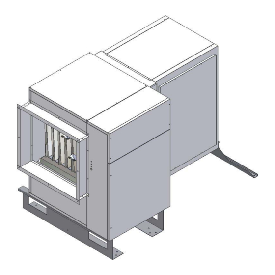
RETURN AIR CONNECTIONS The heater is supplied with 2 return air connecctions one at the rear and one underneath: a. Return air from direction “A”; b. Return air from direction “B”; c. Return air from both direction “A” and “B”. The heater is supplied with a grille at the rear and a blank panel underneath, both the grille and panel are interchangable the fixing points and dimensions of the... -
Page 33: Initial Start-Up
INITIAL START UP VENTILATION Before each attempt ignition • necessary to wait at least 10 seconds. Switch on mains supply to the equipment • Set On/ Standby switch to ON When the burner has ignited check the manometer and, Set the remote control panel switch to VENT check that adjust gas pressure setting to pressure indicated on fans rotation is correct data plate, adjust by turning the solenoid valve screw... -
Page 34: Gas Conversion
GAS CONVERSION The heaters are supplied ready for use with (G20),Natural Gas as per the table below LPG Conversion kits are available from the manufacturer: Natural Gas (G20) TYPE Number of injectors N° Diameter of injectors mm/100 Gas supply pressure 20 mBar Head pressure max 13,0... - Page 35 GAS PRESSURE SETTINGS To regulate the gas inlet pressure : • Connect a manometer to pressure test point (PM) • Ensure that gas supply pressure is sufficient as detailed the table in the manual provided : To regulate the head pressure at the injectors: •...
- Page 36 Gas valve head pressure setting low fire: When setting the gas pressure for propane low fire (first Clockwise increases the pressare. Anti clockwise to stage) contact SF should be open. The low fire decrease the pressare. On completion replace the pressure should be adjusted to the settings shown on plastic cover and seal with paint.
- Page 37 The driven variable pitch pulley drive and fixed fan To check electrical absorption of the motor proceed pulley are factory pre set and are suitable for most as follows: • applications. Insert the ammeter on a phase of the general supply The fan speed can be adjusted on the variable speed line pulley to allow for variations in duct resistances...
-
Page 38: Maintenance
MAINTENANCE It is a requirement that only qualified personnel are Before commencing any maintenance or servicing work allowed to carry out installation commissioning or the heater must be shut down and allowed to cool, and servicing. have the gas and electric supplies to it turned off at the supply cock and isolator respectively. - Page 39 CLEANING OF HEAT EXCHANGER Cleaning of the heat exchanger must be carried out by authorized personnel and is governed by specific regulations. As a guideline cleaning should take place at least once a year, at the beginning of the winter. For this operation proceed as follows: •...
-
Page 40: Fault Finding
FAULT FINDING If heater is not working firstly check the following: • Check electrical supply • Check gas pressure • Check gas pressure is a stated in Technical Data FAULT CAUSE SOLUTION Check main isolator. Check supply cables. No operation No electrical supply Check line fuses. - Page 41 Explosive start up Faulty ignition electrode Change ignition electrode Reposition electrode correctly Incorrect electrode position over the burner bar Faulty burner tube Change burner tube Faulty ignition transformer Change transformer Check that the gas type is suitable for heater Check gas pressure Faulty ignition Check head pressure.
- Page 42 Check that the fan blades are clean. Check that the horizontal and Excessive air temperature due (vertical if fitted) louvres are to poor air flow. sufficiently open (see installation). Check fan is operating correctly with sufficient air flow Faulty thermostat Change thermostat Control box will not reset.
- Page 43 BIEMMEDUE S.p.A. Via Industria, 12 - 12062 CHERASCO (CN) ITALIA Tel. +39 0172 486111 - Fax +39 0172 488270 www.biemmedue.com - e-mail: bm2@biemmedue.com Poiché l’Azienda è costantemente impegnata nel continuo perfezionamento di tutta la sua produzione, le caratteristiche estetiche e dimensionali, i dati tecnici, gli equipaggiamenti e gli accessori, possono essere soggetti a variazione. 10/03/2005 Rev.
Need help?
Do you have a question about the BMP 26 C and is the answer not in the manual?
Questions and answers