
Related Manuals for Magen eco-Energy resilience D Series

Summary of Contents for Magen eco-Energy resilience D Series
- Page 1 35405055 | December 2016 Table of Contents Resilience D Installation guide. © 2016, all rights reserved P a g e www.magen-ecoenergypool.com...
-
Page 2: Preface
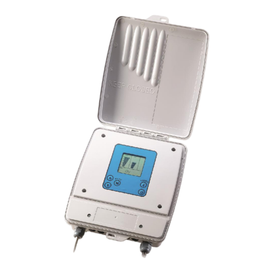
Preface PREFACE Resilience D (model PSC5) is an automatic natural chlorine generator for pool sanitation. The system uses a very low concentration of salt (less than the concentration in a human teardrop) and converts it into free chlorine that destroys algae and bacteria in the pool. After removing the algae and bacteria, the chlorine reverts back into salt. This process of purification continues, making the need of adding extra sanitizing chemicals to the pool virtually unnecessary. - Page 3 Preface ● Wiring of the unit must be performed according to the wiring instructions detailed in this manual or on the front box cover. ● Build-up of flammable fumes can result in a hazardous condition if the cell is allowed to operate without flow.
-
Page 4: Table Of Contents
Preface TABLE OF CONTENTS PREFACE ....................................... 2 safety instructions .................................... 2 PACKAGE CONTENTS ..................................6 Additional materials required (not supplied in package) ......................... 6 SYSTEM OVERVIEW ..................................7 PLUMBING CONFIGURATIONS ..............................8 CELL PLUMBING (WITHOUT DOSING ACID PUMP) ........................8 INSTALLING THE FLOW SENSOR .............................. - Page 5 Preface Salinity readout ....................................24 Normal salt level ..................................24 High salinity indication ................................24 Low salinity indication ................................25 Turbo setting ....................................25 Pool cover function ..................................26 Error messages ....................................27 NO FLOW ....................................27 HIGH TEMPERATURE IN THE UNIT ............................. 27 LOW TEMP ....................................
-
Page 6: Package Contents
Package contents PACKAGE CONTENTS Please unpack your new controller carefully. Do not use a knife or sharp instrument to remove contents. Enclosed in the packing you should find the following: Control Box Flow Switch T & Temp Sensor 4 PVC hose reducer couplings Cell Dosing acid pump... -
Page 7: System Overview
System overview SYSTEM OVERVIEW This installation manual is designed for the pool professional. It assumes the installer has a working knowledge of basic pool-service operations. It is based on actual field installations and the natural flow of progress found to be most efficient. -
Page 8: Plumbing Configurations
Plumbing configurations PLUMBING CONFIGURATIONS CELL PLUMBING (WITHOUT DOSING ACID PUMP) 1. The cell and flow sensor must be installed downstream from the filter and heating devices before any Tees in the return line. The cell may be installed horizontally or vertically as long as is pointing in the flow direction (i.e. -
Page 9: Installing The Flow Sensor
installing the flow sensor INSTALLING THE FLOW SENSOR 1. The flow sensor must be installed before the cell. Make sure that there is no valve between the cell and the flow sensor. The flow sensor may be installed vertically, in an angle, but MUST NOT be installed upside down. This could cause debris to settle in the flow sensor body and restrict the paddle movement. -
Page 10: Horizontal Plumbing Configuration
Installation of dosing acid pump 4. ~54 cm (21 inch) straight 2" PVC pipe for keeping the cell filled with water when there is no flow in the line. HORIZONTAL PLUMBING CONFIGURATION 1. Dosing acid pump 2. Chlorinator Cell 3. Flow Switch Tee The examples illustrated above are with the dosing acid pump installed. - Page 11 Installation of dosing acid pump 4. Open the control box service panel. 5. Find the acid pump connection point marked "acid pump". Insert the signal cable that originates from the pump through the hole at the bottom of the control box and connect it to the acid pump terminal. Make sure the cable is secured and reattach the service panel's cover (see wiring the dosing acid pump, page 14).
- Page 12 Installation of dosing acid pump 14. Cut the supplied tube to the required length - this will become the injection tube. Attach one end to the outlet of the acid pump (right side) and the other end to the injector non-return valve attached to the pipe. Note the arrows impressed on the acid pump transparent cover indicating the suction and injection direction of the acid.
-
Page 13: Mounting The Control Box
Mounting the control box 20. Turn the control box on. Manually operate the acid pump in manual mode for a number of minutes. 21. Make sure the red light on the pump is on, that it is spinning and that acid it sucked from the acid container and injected to the pipe. -
Page 14: Electrical Wiring Of The Control Box
Electrical wiring of the control box CAUTION Do not mount the system above a heater, inside a panel or tightly enclosed area. This can overheat and damage the system. Do not block the vents of the control box, located at its back. 1. -
Page 15: Wiring The Cell
Wiring the cell Alternative wiring (only if not planning to use dosing acid pump) WIRING THE CELL Ensure that the connections are perfectly clean from any debris. Connect the two black wires from the control box to the connectors at the sides of the cell until they "click" together. NOTE: do not extend the original cables leading to the cell. -
Page 16: Wiring The Temperature Sensor
Wiring the temperature sensor WIRING THE TEMPERATURE SENSOR Locate the temperature sensor terminals in the lower part of the control box. Insert the temperature sensor cable through the connector hole in the lower part of the control box and plug it into the temperature sensor socket. Tighten the threaded adaptor firmly, until the cable cannot be pulled out from the box. -
Page 17: Starting Up
Starting up STARTING UP BEFORE ADDING THE SALT 1. Balance the chemicals: See the section titled "Understanding the chemistry" on page 35 for recommended water balance. Remove metals from the water using a phosphate-free metal remover and test the water to ensure that phosphate levels are lower than 100 ppb (parts per billion). -
Page 18: Adding The Salt
Starting up ADDING THE SALT 1. Measure the pre-existing salinity of your pool. Previous chlorine use may cause the salinity reading to be higher due to residual salt in the chlorine. 2. Determine how much salt is needed from the Salinity Demand Table on the page 19. This table is based on a salt concentration of 3500 ppm (approximately ⅓... -
Page 19: Salinity Demand Table (In Kg.)
Starting up Salinity demand table (in kg.) Salt level before addition (in ppm) 1000 1500 2000 2500 3000 3500 4500 How much salt to add? (In kg.) Identify the current salt concentration at the top of the chart (e.g 1000 ppm). Then find the size of your pool on the left (e.g. -
Page 20: Operating Instructions
Operating instructions OPERATING INSTRUCTIONS FILTRATION Proper filtration is critical for maintaining clean and healthy water. It is typically required in the pool industry that all the water of the pool pass through the filter at least one and a half (1½) times per day (at least eight hours in most pools). -
Page 21: Basic Operation
Basic operation BASIC OPERATION The natural chlorine generator produces a pure form of chlorine to sanitize and oxidize the pool water. The chlorine residual needs to be maintained at 1 to 3 ppm. This may be tested using a standard kit or by your local pool store. To obtain the optimal residual buildup of chlorine, the best time to run your filter is in the early morning and after 4pm when there is less UV to destroy the chlorine produced, leaving chlorine in the pool to oxidize the unwanted foreign matter. -
Page 22: Turning The Unit On
Basic operation TURNING THE UNIT ON 1. Ensure that the main circulation pump is on. 2. Press the button. 3. The controller turns on and automatically executes the following actions: The system goes to the last setting before it was turned off. The main screen is active Turbo time (if previously in this mode) goes back to zero (initialized). -
Page 23: Operating Actions
Basic operation OPERATING ACTIONS In order to change the operation statuses of the system use the following operating actions: Increasing chlorine output Press the button: 1,2,3….100%. A quick press on the button causes one-digit increments; a long press runs the digits faster. A 0-100 display appears in the numerical display according to user settings, and the setting output bar blinks, until the output level reaches the desired setting. -
Page 24: Salinity Readout
Basic operation SALINITY READOUT NOTE: the salt readout takes up to one minute to test and display the salt level. NOTE: The chlorinator cell should be tested as lime-scale build up on its blades may affect the readings. Clean the blades if necessary. If the cell is clean and readings are still inaccurate please refer to the troubleshooting section of this guide, page 38. -
Page 25: Low Salinity Indication
Basic operation Low salinity indication Below 3000 ppm – the low salinity bar and the saltshaker icon are turned on. Below 2000 ppm – the low salinity bar and saltshaker icons blink. In all low salinity situations and alarms the unit continues its operation. -
Page 26: Pool Cover Function
Basic operation Turbo mode additional information – Counting is performed only when the unit is ON. During the first 5 seconds in Turbo screen, additional presses on the Turbo button increases the timer in increments of 12 hours with each press: 12, 24, 48, 72 or 0 hours. Cancelling the Turbo option reverts back to the previous output selection. -
Page 27: Error Messages
Basic operation ERROR MESSAGES NO FLOW The "faucet" icon is displayed and "NO FLOW" message appears on the numerical display. If the faucet icon blinks it means that the flow switch is in "transient" position. Wait a few seconds for the icon to stop blinking and remain on the display. If the icon continues to blink, verify that you have proper flow without air bubbles in the cell pipeline. -
Page 28: No Cell
Basic operation NO CELL If the cable is disconnected, the salinity is much too low (below 1000 ppm) or the cell has collected large amounts of scale deposits a "NO CELL" indication will appear on the numerical display and the unit will reduce the power output to 0. -
Page 29: Ph Control
pH control PH CONTROL The dosing acid pump enables the system to reduce pH levels by periodically infusing small amounts of acid into the pool. More acid in the water balances the pH levels, less acid units allow pH to rise. NOTE: Test the pool water regularly and adjust as necessary. -
Page 30: Cell Cleaning Mode
pH control CELL CLEANING MODE The dosing acid pump system ensures the cell remains clean by automatically washing it with acid when the circulation pump is off. The factory preset allows a cell wash after the circulation pump logs at least 6 hours of run time (e.g. -
Page 31: Acid Pipe Reminder
Maintenance ACID PIPE REMINDER The Check Vavle and the internal tube of the dosing acid pump unit require replacing every 180 days, therefore the system is set to begin counting down 180 days upon first operation. An "ACID PIPE" message appears on the numerical display every 180 days, when the check valve and internal tube requires replacing. -
Page 32: Cleaning Using The Cleaning Cap
Winterizing Cleaning using the cleaning cap 1. Disconnect the wires connecting the control box to the cell. 2. Remove the cell from the line by unthreading the barrel unions from the cell ends. 3. Remove the black O'ring on one end of the cell. 4. -
Page 33: Replacing The Preistaltic Tube Of The Dosing Acid Pump
Replacing the preistaltic tube of the dosing acid pump REPLACING THE PREISTALTIC TUBE OF THE DOSING ACID PUMP It is recommended to replace the check valve and internal tube of the dosing acid pump before starting a new bathing season and/or every six months during the season. Please contact your local dealer to obtain a new tube. The internal tube requires replacing when ACID PIPE message is visible. - Page 34 Replacing the preistaltic tube of the dosing acid pump Gently insert the tube back into place making sure Return the transparent cover to its place. the black bases of the tubes are tightly in their slots in the casing. Check for leaks and leave the pump running in manual mode for 10-20 minutes in order to release the air in the system.
-
Page 35: Understanding The Chemistry
If the water chemistry needs adjustment, your authorized dealer or most pool stores can supply you with the appropriate chemicals and procedures. We recommend either taking a copy of the Water Balance Table to the pool store, or notifying the pool store that you are using Magen eco-Energy's natural salt chlorine generator (model PSC5). - Page 36 Understanding the chemistry pH is a measure of the acidic or basic solution. A scale of 0 to 14 is used to measure pH. Pure water has a pH of seven (neutral), acid solution have a pH of less than seven, and basic (alkali) solutions have a pH of more than seven. The recommended range is 7.2 to 7.6;...
-
Page 37: Saturation Index
Saturation index SATURATION INDEX Test the water for pH, Alkalinity, Calcium hardness and temperature, and then follow the simple steps detailed below: 1. Write your pool pH level here pH: _______________ 2. Find your Alkalinity level in the chart below, And write the corresponding Alkalinity factor here: Alkalinity Factor: _________________ Pool Alkalinity... -
Page 38: Troubleshooting
Troubleshooting TROUBLESHOOTING NOTE: Evaluating the possible causes for each problem from top to bottom (first to last) will void extra labor. Problem Possible Causes What to do System is turned off Turn the system on to the desired setting ... - Page 39 Troubleshooting Problem Possible Causes What to do Insufficient water This is normal if there is air in the lines or for a few flows from pump to minutes at initial startup flow sensor and cell Clean filters and strainers ...
- Page 40 Troubleshooting Problem Possible Causes What to do Salinity high - Enough This does not harm the natural generator, but salt has been added simply indicates that the salt level is high causing the red light It is recommended to periodically test the salt above the power levels by a professional.
- Page 41 Troubleshooting Problem Possible Causes What to do Salinity is very high Drain part of the water and refill the pool to bring the salinity levels down. See troubleshooting section – salinity high (above) for more information SHRT CELL message is ...
- Page 42 Troubleshooting Problem Possible Causes What to do Metals in the fill water may Have a pool professional test the pool water. have been oxidized If high in metals use phosphate-free metal Colored water remover Algae may be trying to form ...
-
Page 43: Dosing Acid Pump Troubleshooting
Dosing acid pump troubleshooting DOSING ACID PUMP TROUBLESHOOTING WARNING! You are about to manipulate components which are in contact with concentrated Muriatic Acid. USE PROTECTIVE GLOVES, GOGGLES and CLOTHING FOR YOUR SECURITY. In case of involuntary contact with acid, flush the affected areas with running water. In case of contact with eyes, flush with water and contact a physician! Problem Possible Causes... - Page 44 Dosing acid pump troubleshooting Problem Possible Causes What to do Hydrochloric (Muriatic) acid Replenish acid in the container or replace container is empty with a new one After replacing acid container, enter manual mode and run the system for 1-2 sequences in order to release air from the system (priming) ...
Need help?
Do you have a question about the resilience D Series and is the answer not in the manual?
Questions and answers
I have a Resilience D-Series which has stopped generating chlorine. The display is showing a wrench in the special icons section on the right side of the display. What does that mean? What do I need to do to fix this when the wrench icon is showing? By the way, the cell was replaced back in 2022, so it should still be fine. See attached image.