Table of Contents
Advertisement
Quick Links
Installation and operating instructions
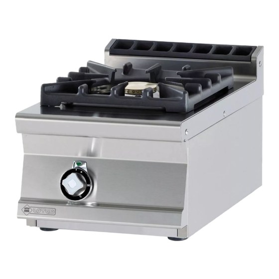
KITCHEN WITH OVEN FOR
PROFESSIONAL USE
PC1T-64G PC2T-68G PC3T-612G CF2-68G CF3-612GV CF2-68GEM
CF3-612GEMV CFM2-68GEM CFM3-612GEMV
Model LIBR.ISTR.PC1T-CF2G-GE
Code 563015100
Review 1
Edition date 20/06/2019
Language English
LOTUS S.p.A.
Via Calmaor, 46
31020 San Vendemiano
+39 0438 778020
+39 0438 778277
Translation of the original instructions
Advertisement
Table of Contents

Subscribe to Our Youtube Channel
Related Manuals for Lotus PC1T-64G


Summary of Contents for Lotus PC1T-64G
- Page 1 Installation and operating instructions KITCHEN WITH OVEN FOR PROFESSIONAL USE PC1T-64G PC2T-68G PC3T-612G CF2-68G CF3-612GV CF2-68GEM CF3-612GEMV CFM2-68GEM CFM3-612GEMV Model LIBR.ISTR.PC1T-CF2G-GE Code 563015100 Review 1 Edition date 20/06/2019 Language English LOTUS S.p.A. Via Calmaor, 46 31020 San Vendemiano +39 0438 778020...
-
Page 2: Table Of Contents
Contents Contents INTRODUCTION ......................... Installation drawing ........................Components..........................GENERAL INFORMATION......................Declaration of compliance......................User information, RAEE Directive on waste electrical and electronic equipment ......Technical data table ........................INSTALLATION........................... Delivery checks ..........................Removing the packaging ......................Mechanical installation ......................... Electrical/gas connections ......................BURNERS TECHNICAL DATA TABLE (ITGB)................ -
Page 3: Introduction
INTRODUCTION 1 INTRODUCTION Installation drawing FIG. 1 PC.. A Data Plate C Gas connection Translation of the original instructions... - Page 4 INTRODUCTION FIG. 2 CF.. A Data Plate B Gas connection C Electrical connection Translation of the original instructions...
-
Page 5: Components
INTRODUCTION Components FIG. A 1 By-pass FIG. B 1 Pilot bracket screw 2 Pilot bracket 3 Pilot air bushing 4 Pilot injector 5 Injector screw 6 Spring 7 Extends drainage Translation of the original instructions... - Page 6 INTRODUCTION FIG.C (FLAMES) 1 Flame injector 2 Air adjustment 3 Pilot FIG. E 1 Oven by-pass Translation of the original instructions...
- Page 7 INTRODUCTION FIG. D 1 Ignition spark plug 2 Injector 3 Extends drainage 4 Air adjustment Translation of the original instructions...
- Page 8 INTRODUCTION STATIC ELECTRIC OVEN WIRING DIAGRAM (D) 1 Switch 2 Oven lamp 3 Power supply terminal board 4 RS Upper resistor 4 RG Grill resistor 4 RI Lower resistor 5 White indicator light 6 Green indicator light 7 Timer 8 Thermostat Translation of the original instructions...
- Page 9 INTRODUCTION WIRING DIAGRAM MULTIFUNCTION ELECTRIC OVEN (E) 1 Switch 2 Oven lamp 3 Power supply terminal board 4 Motor fan 5 RS Upper resistor 5 RG Grill resistor 5 RI Lower resistor 5 RC Circular resistance 6 White indicator light 7 Green indicator light 8 Timer 9 Thermostat...
-
Page 10: General Information
GENERAL INFORMATION 2 GENERAL INFORMATION Declaration of compliance The manufacturer declares that the appliances comply with the requirements of the regulation GAR 2016/426 for the gas part and directive 2014/30/EU,2014/35/EU for the electrical part. Installation must be performed in compliance with current regulations, especially with regard to ventilation of the premises and the exhaust gas evacuation system. -
Page 11: User Information, Raee Directive On Waste Electrical And Electronic Equipment
RATED BURNER CAPACITY (kW) RATED TOTAL GAS FITTING Gas oven MODEL DIMENSIONS GAS FLOW (kW) ISO 7-1 7 kW 10 kW GN1/1 4 kW PC1T-64G 40x60x29h R 1/2GM PC2T-68G 80x60x29h R 1/2GM PC3T-612G 120x60x29h R 1/2GM CF2-68G 80x60x90h R 1/2GM... -
Page 12: Installation
INSTALLATION 3 INSTALLATION Delivery checks On delivery, it is important to check the following: · External conditions of the packaging · The general status of the equipment · The conformity of the model with the information in the technical data plate and the instruction manual ·... - Page 13 INSTALLATION Warning Installation operations, any conversion to other types of gas and start-up must only be performed by qualified personnel, in accordance with current regulations. Gas systems, electrical connections and premises where the appliances are installed must comply with current regulations in the country of installation;...
- Page 14 INSTALLATION valve and fast-closing valve. Once installation is complete, make sure that there are no gas leaks from the fittings; to do this, do not use a naked flame but substances that do not cause corrosion, such as solutions of soapy water or leak detectors.
- Page 15 INSTALLATION - "A" type devices (see data plate) "A" type appliances must discharge combustion products into appropriate hoods, or similar devices, connected to an efficient fume stack or directly to the outside. (Natural evacuation) Fig. 1 If this is not possible, using an air suction device connected directly to the outside is permitted (Forced Evacuation) Fig.2, having a flow capacity not lower than the value defined in point 4.3 of the UNI-CIG 8723 standard.
- Page 16 INSTALLATION 1 Windproof fume stack (fig.3) - Extractor hood (fig.4) 2 Servo system "B11" type appliances are supplied on request with a hood or a hood and windproof fume stack to be assembled and delivered separately. Translation of the original instructions...
-
Page 17: Burners Technical Data Table (Itgb)
BURNERS TECHNICAL DATA TABLE (ITGB) 4 BURNERS TECHNICAL DATA TABLE (ITGB) Burners technical data table Technical data table - Burners PCCF S60G 12.68 kWh/KG 12.87 kWh/KG 9.45 kWh/m3st. BUTANE PROPANE METHANE H 30 mbar 37 mbar 20 mbar Burner max 7 kW-min 1.8 kW ... -
Page 18: Instructions For Use
INSTRUCTIONS FOR USE 5 INSTRUCTIONS FOR USE General information This appliance must only be used for its expressly intended purpose for cooking or heating food. Any other use is considered improper. The appliance is also intended for industrial use and must only be used by personnel trained for use and aware of the risks that the hot element entails. -
Page 19: Switching The Main Burner Off
INSTRUCTIONS FOR USE Switching the main burner off · Turn the knob into position . The burner turns OFF and only the pilot flame remains ON Turning the appliance off · Press and turn the gas cock knob to position "0". This control blocks the gas supply to both the main burner and the pilot burner ... -
Page 20: Igniting The Grill Burner
INSTRUCTIONS FOR USE Igniting the Grill burner To IGNITE, turn the knob to the left from the "0" position into position hold the knob down until the gas ignites. After ignition, hold the knob pressed for about 10 seconds to allow the thermocouple to heat up and then release it. - Page 21 INSTRUCTIONS FOR USE The hot air circulated by the fan is distributed throughout the oven chamber to ensure uniform cooking. Since the chamber is heated uniformly, different foods can be cooked simultaneously on several levels. Turn the knob to the symbol (hot air) and set the desired temperature. The is absolutely no need to preheat the oven, since the chamber heats up quickly once the hot air is activated.
- Page 22 INSTRUCTIONS FOR USE After setting the cooking time, turn the thermostat knob (see figure) to the right, setting it at the desired temperature Caution When the oven is operating, the door must not remain open as it could overheat and damage ...
-
Page 23: Maintenance
MAINTENANCE 6 MAINTENANCE Routine When using the appliance over time, it is essential to perform regular maintenance to ensure safe operation. We therefore recommend stipulating a service contract. Caution Maintenance must only be performed by specialist personnel in compliance with current ... -
Page 24: Substituting The Nozzle In The Oven Burner
MAINTENANCE Warning After conversion to another type of gas, update the technical data plate to indicate the type of gas for which the appliance has been converted. Substituting the nozzle in the oven burner · Remove the base of the oven ·... - Page 25 MAINTENANCE To replace such parts, proceed as follows: · GAS TAP: after disassembling the front panel, unscrew the gas connection screw couplings, remove the coupling, replace the faulty parts and install the new ones in sequence · THERMOCOUPLE: unscrew the pilot burner coupling, unscrew the gas tap coupling in the same way and replace the element ...
-
Page 26: Cleaning
CLEANING 7 CLEANING Routine cleaning Caution The use of flammable fluids to clean the appliance is forbidden To ensure hygiene and the durability of the appliance, perform external cleaning on a regular basis, taking care not to damage the cables and the electrical connections. Before starting cleaning, disconnect the appliance from the power supply.
Need help?
Do you have a question about the PC1T-64G and is the answer not in the manual?
Questions and answers