Table of Contents
Advertisement
Quick Links
Advertisement
Table of Contents

Subscribe to Our Youtube Channel
Summary of Contents for Danaher Motion ACOMEL K 4000
- Page 1 K4000 - USER MANUAL 25-11-03 S476 -gb-0348...
- Page 2 Empty page Page 2 / 48 User Manual K4000 S476-gb-0348...
-
Page 3: Table Of Contents
TABLE OF CONTENT Safety instructions Information on the Operating Manual The Basic Safety Rules Working instruction Overspeed protection Proper installation Responsibility A comprehensive range of product Product basics Main technical data Current and Power ratings Dissipation and Dynamic Braking Resistors ratings Type Part Numbering Overload protection Connecting the K4000 to a transformer... - Page 4 Connecting the PTC - motor temperature protection The analog input AI1 Inhibit the analog speed reference input Selecting one of the pre-set speeds Connecting the dynamic braking resistor Programming the K4000 The Menus The User Interface PC560 QUICK START Compulsory connections The characteristic Voltage / Frequency or Power / Frequency The input of the parameters The START...
-
Page 5: Safety Instructions
Safety instructions Information on the Operating Manual This operating manual applies to the K4000 frequency inverter family. It describes the connections and basic functions of the standard models. CAUTION! Danger of death by electrocution CAUTION! Absolutely essential FORBIDDEN! Incorrect operation, may lead to damage. The Basic Safety Rules First read the user manual Before installing and commissioning, it is important for such personal to read carefully... -
Page 6: Overspeed Protection
The converter control board uses a large number of MOS (Metal Oxide Semiconductor) which are highly sensitive to electrostatic charge. To avoid any damages to the control board • wear an earthing strap and always handle the board by the extractors •... -
Page 7: A Comprehensive Range Of Product
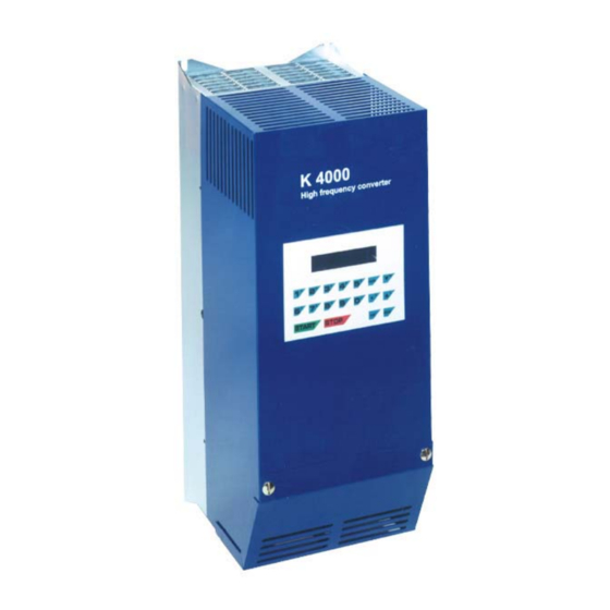
A comprehensive range of product Product basics The K4000 is a high frequency inverter designed for application up to 4000 Hz. The K4000 family consists of several models with output ratings from 5 to 120 kVA. the selective harmonic suppression -SHS - developed by DANAHER-MOTION, is aimed at reducing motor losses and winding stresses without output filter. -
Page 8: Dissipation And Dynamic Braking Resistors Ratings
Dissipation and Dynamic Braking Resistors ratings Model Dissipation Braking resistors Ω / Watts - external Watts KT4005 22Ω/400W KT4010 22Ω/400W KT4015 22Ω/400W KT4020 15Ω/1200W KT4030 15Ω/1200W KT4040 1200 6Ω/1500W KT4060 1800 6Ω/1500W 2700 KT4090 4Ω/2000W 3600 KT4120 4Ω/2000W Type Part Numbering Standalone IP20 units KT40xx-00 Without PC560 and external dynamic braking resistor... - Page 9 The dimensions of the KT4000 ∅ F Model Overall Dimensions Mounting Dimensions Weight Screws KT4005 4 x M6 29 kg KT4010 KT4015 KT4020 KT4030 KT4040 4 x M10 71 kg KT4060 KT4090 91 kg KT4120 All dimensions are in mm Cabinet enclosure 1.
-
Page 10: The 19" - Rack Versions, Kl4000
The 19” – rack versions, KL4000 Current and Power ratings Model Output Current A Typical motor power Nominal Continuous Peak kW @ 3 x 400 V KL4005 KL4010 KL4015 KL4020 KL4030 All units are rated for a maximal input current of 32 A Input current: Input terminals: 10 mm... -
Page 11: K4000 - Drive Overview
K4000 - Drive overview The KT4005, KT4010, KT4015, KT4020 and KT4030 Display 2 lines of 20 Characters Serial link RS485 to control board Terminal bloc removable cover Control board with signal control terminals X2/61 to X2/80 CN4 – RS232 / RS422 / D-Sub 9 pins switchable for direct programming and controlling of the drive using a PC in terminal mode... -
Page 12: The Kt4040 And Kt4060
The KT4040 and KT4060 The control board Switching power supply board and control signal connecting board IGBT drivers Chopper Power terminal driver bloc X1 Driver braking chopper Input circuit breaker Page 12 / 48 User Manual K4000 S476-gb-0348... -
Page 13: The Kt4090 And Kt4120
The KT4090 and KT4120 The Twin- Chopper drivers The 3 input fuses S476-gb-0348 S476-gb-0348 User Manual K4000 User Manual K4000 Page 13 / 48 Page 13 / 48... -
Page 14: The 19" - Rack Version Kl4000
The 19” – rack version KL4000 The terminal blocks, connection for front access: Circuit breaker X2 control terminals power terminals X1 The terminal blocks, connection for access from the back X2 control terminals X1 power terminals Page 14 / 48 User Manual K4000 S476-gb-0348... -
Page 15: K4000 - Terminals Descriptions
K4000 - Terminals descriptions Input circuit breaker This is not a power switch The converter is protected against ground short circuit by a fast circuit breaker. Resetting is performed manually by pushing a lever, during this operation tripping is disabled, so that the converter is no longer protected. -
Page 16: Terminal Bloc X1 Of The Kt4040 And The Kt4060
Terminal bloc X1 of the KT4040 and the KT4060 Terminal bloc X1 of the KT4090 and the KT4120 3 Fuses 160 A Super quick-acting Use only original model Page 16 / 48 User Manual K4000 S476-gb-0348... -
Page 17: View Of The Control Terminal Bloc X2
View of the control terminal bloc X2 The Power switching board with terminals X2/1 – 60 and the D-sub connectors CN2 and CN3. Reference P/N HB7451 CN3 - 9 pins D-Sub connector for remote display DD550 only. A PC560 must be Connected to CN2. -
Page 18: The + 25 Vdc - Auxiliary Power Supply
The + 25 VDC - Auxiliary Power Supply On the control terminal bloc X2, they are a number of terminals where the +25 VDC internal power supply is available. This power supply is only available for the inputs and outputs of the K4000, no other device must be connected. - Page 19 Term Short K3000 Name Description How to activate X2 Ref. SAN1 Analog output 1 Internal programmable AGND Analog ground parameter 0 ... 10 VDC SAN2 Analog output 2 Internal programmable AGND Analog ground parameter 0 ... 10 VDC CSM+ Catch a spinning motor To activate apply +25 VDC CSM- Catch a spinning motor...
-
Page 20: Compulsory Connections
Compulsory Connections Some of the connections are optional, depending on what functions are required and whether these functions are to be accessed in digital mode from K or from the X2 . For further information, refer to the bloc diagram. Even to ERMINAL control the drive through the user interface PC560 , the following connections are compulsory :... -
Page 21: The Digital And Analog Programmable Outputs And Inputs
The digital and analog programmable outputs and Inputs Selection of the MCM reference The selection of one of the 4 MCM sensitivity level is made by applying 25V to the 2 terminals X2/6 and / or X2/7 using a BCD coding. Sensitivity no 25 V applied 25 V to X2/6... -
Page 22: The Relay Contact Outputs
The relay contact outputs Digital outputs No 1, 2, 3, 4 and 5 Contact rating 25 VDC - 100 mA Output relay 1- contact normally open Output relay 1 - middle point Output relay 1 - contact normally close Terminals 25, 26, 27: relay No 1 Terminals 28, 29, 30: relay No 2 Terminals 52, 53, 54: relay No 3 Terminals 55, 56, 57: relay No 4... -
Page 23: The Programmable Analog Output San1 And San2
The programmable analog output SAN1 and SAN2 The output is 0 ... 10 V SAN1 Maximal load 10 mA The load must be ≥ 4.7 k Ω respectively ≤ 10 k Ω AGND Use one of the 0 V (electronic ground) on the terminal bloc X2 for the return. -
Page 24: Connecting The Ptc - Motor Temperature Protection
Connecting the PTC - motor temperature protection The PTC - motor temperature protection sensor will be connected between terminal X2/58 and X2/59. This input is protected against overvoltage by a Zener diode. In case of overvoltage on this input, the Zener diode will blow and must be replaced for proper operation. -
Page 25: Connecting The Dynamic Braking Resistor
Connecting the dynamic braking resistor The dynamic braking resistor is a potential free stainless steel heating resistor. The 2 terminals of the resistor connect to the 2 power terminals X1/ B. The kit shown on the picture consists of the resistance with a 200°C temperature sensor (opening contact), a protection grid and mounting accessories. -
Page 26: Programming The K4000
Programming the K4000 The Menus • Menu A Inverter parameters • Menu B Part 1 – Operation related parameter Part 2 – Motor related parameter • Menu C Allocation of the digital and analog outputs • Menu D The parameters accessible in START mode •... -
Page 27: Quick Start
QUICK START OR THE MINIMUM INPUTS TO RUN YOUR MOTOR WITH KEYPAD CONTROL 3. Compulsory connections Check that all compulsory connections according page 20, have been done. 4. The characteristic Voltage / Frequency or Power / Frequency For optimal performances of the motor and its frequency inverter, it is important that Fmax F n=Fm ax U s/Fs=pt1... -
Page 28: The Start
In the column “Display” is represented the text shown on the display Display Value Key to Comments press 2ndF B 0=F 1=GB 2=D 3=I 4=E ENTER Selection of the English language Menu locking 0=B,C ENTER Access locking through X2/47-48 Assign the Start / Stop function to the Start/Stop (choice) ENTER PC560... -
Page 29: The Programmable Parameters
The programmable parameters Menu A : Inverter Related Parameters Access in STOP mode only by entering 2ndF A Display Description Values Max. current. Display the maximum output current of the K4005 = 10 A (A) = inverter. This parameter is related to the drive K4010 = 15 A rating and is used to protect the drive in overload K4015 = 23 A... - Page 30 Menu B – Part 1 : Operation related parameters (continued …) Display Description Motor reversing If you want to lock any reversing of the rotating direction of the motor you can do it here. Enter: 0=NO , 1=YES Reversing forbidden Reversing according assignment either from K ERMINAL Motor reversing...
-
Page 31: Menu B - Part 2: Motor Related Parameters
Menu B - Part 2: Motor related parameters This section of the menu B related to parameters that are linked to a specific partition. 32 partitions can be entered and recorded. They can be different motors or specific values for the same motor: for example if you want to limit the maximum speed at a lower value for reverse operation you enter a new partition and specify the speed you want. - Page 32 Menu B – Section 2 : Motor related parameters (cont…) Display Description Motor current Enter here the reference current of the motor. Normally a value of maximum 150% of the nominal current of the motor is used. Iref (A) = Any lower value can be set.
- Page 33 Menu B – Section 2 : Motor related parameters (cont…) Display Description If you have selected the Freq. ctrl source from the T Pre-set Frequency 1 ERMINAL in the Menu B- Part 1, you have the possibility to define LOCK up to 3 pre-set speeds.
- Page 34 Menu B – Section 2 : Motor related parameters (cont…) Display Description MCM - 0 = Abs. Motor Current Monitoring: functions =, 1 and 2 can be allocated to one of the relay output. 1 = SH 2 = DTO •...
- Page 35 Menu B – Section 2 : Motor related parameters (cont…) Display Description FCC duration DC braking current duration. This function, when activated, is automatically initiated after a STOP command, when the DC bus (s) = reaches 10% ( ≤ 35 V). Value of the DC injected braking current.
-
Page 36: Menu C : Allocation Of The Relay Outputs
Menu C : Allocation of the relay outputs Access in STOP mode only The digital outputs are : relay RE1, output No 1 = terminals 25, 26, 27 relay RE2, output No 2 = terminals 28, 29, 30 relay RE3, output No 3 = terminals 52, 53, 54 relay RE4, output No 4 = terminals 55, 56, 57 relay RE5, output No 5 = terminals 22, 23, 24 The digital outputs are located on the T... -
Page 37: Menu C : Allocation Of The Analog Output
Menu C : Allocation of the analog output Access in STOP mode only Functions to allocate to Comments on the allocated function one of the digital outputs The allocated relay switches if the heatsink temperature Converter temp (NTC) exceeds 70°C, tolerance ± 3°C.. Relay nr. -
Page 38: Menu Ey : Reversing From K Pad
Menu E : reversing from K 2ndF E will reverse the rotation direction of the motor, but only if 0 has been programmed in the corresponding step of the Menu B - part 1 . If reversing from the X2 has been selected the following message will be displayed: ERMINAL “Reversing assigned to T. -
Page 39: Display Of The Digital I/O Status
Display of the digital I/O status With the display bloc 4 you can visualize, using the 2 lines of 20 characters, the status of the digital Inputs and Outputs available on T X2. Each ERMINAL assigned character show a 0 if the corresponding input is not activated or low , respectively a 1 if activated or high. -
Page 40: Menu H : Display Of The Last 8 Failures
Menu H : Display of the last 8 failures Allow to display the last 8 failures recorded in a FIFO table. Menu I : RESET 2ndF I will RESET the drive and allow to start again if the cause of the failure has been removed. -
Page 41: The Tachobox Option
The Tachobox Option TACHOBOX-1 Senso Senso Signal Digital speed signal CDI+ Digital speed CDI- +25V +25V AGND 48 AGND Signal 0,7 – 1,4V 2,3 – 3,5V 114,5 TS35 S476-gb-0348 User Manual K4000 Page 41 / 48... -
Page 42: Galvanic Insulation Of The Power Circuitry
Galvanic insulation of the power circuitry Function This option includes a EMC input line filter and the galvanic interruption of the power connections in front of the filter when the drive is in STOP mode, the control part of the inverter remains powered. Principle F>0 START... -
Page 43: K4000 - List Of Error Messages
K4000 – List of Error messages Messages Explanation Fatal error. No communication between the K PC580 and No communication the drive. Check connecting cable. The speed control function has been assigned to T Freq ctrl assigned on ERMINAL X2 in menu B and you try to change the speed from the K T.Block You selected the partition coding via the terminal block and no Partition coding is missing... -
Page 44: Part Numbers For Spares, Options And Accessories
Part numbers for spares, options and accessories Part Number Spare HB7701 Control board HB7451 Power supply board HPC560DX0 for mounting in cabinet door, without cable H9000099-LL Cable for PC560DX0, LL is the length in meter HPC560DX1 Keypad with housing for remote control, without cable H9000103-LL Cable for PC560DX1, LL is the length in meter Braking resistors without protective grid... -
Page 45: Assistance And Trouble Shooting
Assistance and Trouble shooting All our products are manufactured in accordance with an accurate quality process. Before delivery they are checked for many hours under power. The quality system and production process guarantee that all products are shipped free of default. The respect of the installation procedure describes in this manual and a correct definition of the application should avoid any commissioning problems. -
Page 46: Overview Of Menu A, B And C
Overview of Menu A, B and C Menu A: Converter parameters Display Please copy Menu A data Max. current. Softwareversion Display Date of delivery MCM - 3 = none Serial number Current Iabs 1 Running timer Current Ish 1 Time power applied Current IDTO 1 Current... -
Page 47: Declaration Of Conformity
DECLARATION OF CONFORMITY Danaher Motion declare under our sole responsibility that the products of the family K4000 are exclusively designed for incorporation in an other machine. The operation of the product is submitted to the conformity of the complete equipment, following the provisions of the directive... - Page 48 Page 48 / 48 User Manual K4000 S476-gb-0348...
Need help?
Do you have a question about the ACOMEL K 4000 and is the answer not in the manual?
Questions and answers