
Subscribe to Our Youtube Channel
Related Manuals for Aaeon AGP-3155


Summary of Contents for Aaeon AGP-3155
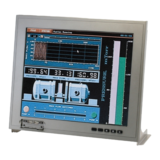
- Page 1 A G P - 3 1 5 5 T o u c h P a n e l P C AGP-3155 Intel® Core™ i7/i5 Processor Rugged Touch Panel Computer With 15” TFT LCD & Two PCI/PCIe expansion slots AGP-3155 Manual 1st Ed March 2011...
- Page 2 AAEON, assumes no liabilities resulting from errors or omissions in this document, or from the use of the information contained herein. AAEON reserves the right to make changes in the product design without notice to its users.
- Page 3 R u g g e d E x p a n d a b l e A G P - 3 1 5 5 T o u c h P a n e l P C Acknowledgments Award is a trademark of Award Software International, Inc. IBM, PC/AT, PS/2 and VGA are trademarks of International Business Machines Corporation.
- Page 4 T o u c h P a n e l P C Packing List Before you begin installing your card, please make sure that the following materials have been shipped: • AGP-3155 • Jumper Cap • Easy stand & 4 screws •...
- Page 5 R u g g e d E x p a n d a b l e A G P - 3 1 5 5 T o u c h P a n e l P C Safety & Warranty 1. Read these safety instructions carefully. 2.
- Page 6 R u g g e d E x p a n d a b l e A G P - 3 1 5 5 T o u c h P a n e l P C The equipment does not work well, or you cannot get it to work according to the users manual.
- Page 7 R u g g e d E x p a n d a b l e A G P - 3 1 5 5 T o u c h P a n e l P C Below Table for China RoHS Requirements 产品中有毒有害物质或元素名称及含量 AAEON Panel PC/ Workstation 有毒有害物质或元素 部件名称 铅 汞...
-
Page 8: Table Of Contents
R u g g e d E x p a n d a b l e A G P - 3 1 5 5 T o u c h P a n e l P C Contents Chapter 1 General Information 1.1 Introduction.............. - Page 9 R u g g e d E x p a n d a b l e A G P - 3 1 5 5 T o u c h P a n e l P C 2.16 RS-232 Pin Header (COM3~4) ....... 2-9 2.16 SATA Connector (SATA 1~3) .........
-
Page 10: Chapter 1 General Information
R u g g e d E x p a n d a b l e A G P - 3 1 5 5 T o u c h P a n e l P C Chapter General Information Chapter 1 General Information... -
Page 11: Introduction
A G P - 3 1 5 5 T o u c h P a n e l P C 1.1 Introduction AGP-3155 is the series product of the Rugged Expandable Touch ® Panel Solution. It adopts Intel Core™ i7/i5 processor with two DDR3 800/1066 MHz SODIMM up to 8 GB. -
Page 12: Feature
R u g g e d E x p a n d a b l e A G P - 3 1 5 5 T o u c h P a n e l P C 1.2 Feature 15” XGA (1024 x 768) TFT LCD Display ®... -
Page 13: Specification
R u g g e d E x p a n d a b l e A G P - 3 1 5 5 T o u c h P a n e l P C 1.3 Specification System ® Intel Core™... -
Page 14: Dimension
R u g g e d E x p a n d a b l e A G P - 3 1 5 5 T o u c h P a n e l P C Mounting Panel/ Desktop Dimension 15.36”... - Page 15 R u g g e d E x p a n d a b l e A G P - 3 1 5 5 T o u c h P a n e l P C Display Type 15” Color TFT LCD Max.
- Page 16 R u g g e d E x p a n d a b l e A G P - 3 1 5 5 T o u c h P a n e l P C 1.4 Dimension I/O interface Chapter 1 General Information...
-
Page 17: Chapter 2 Hardware Installation
R u g g e d E x p a n d a b l e A G P - 3 1 5 5 T o u c h P a n e l P C Chapter Hardware Installation Chapter 2 Hardware Installation... -
Page 18: Safety Precautions
R u g g e d E x p a n d a b l e A G P - 3 1 5 5 T o u c h P a n e l P C 2.1 Safety Precautions Always completely disconnect the power cord from your board whenever you are working on it. -
Page 19: Board
R u g g e d E x p a n d a b l e A G P - 3 1 5 5 T o u c h P a n e l P C 2.2 Location of Connectors and Jumpers of the Main Board Component Side Chapter 2 Hardware Installation... - Page 20 R u g g e d E x p a n d a b l e A G P - 3 1 5 5 T o u c h P a n e l P C Solder Side Chapter 2 Hardware Installation...
-
Page 21: List Of Jumpers
R u g g e d E x p a n d a b l e A G P - 3 1 5 5 T o u c h P a n e l P C 2.3 List of Jumpers There are a number of jumpers in the board that allow you to configure your system to suit your application. -
Page 22: Setting Jumpers
R u g g e d E x p a n d a b l e A G P - 3 1 5 5 T o u c h P a n e l P C 2.5 Setting Jumpers You configure your card to match the needs of your application by setting jumpers. -
Page 23: Cmos Setting (Cmos1)
R u g g e d E x p a n d a b l e A G P - 3 1 5 5 T o u c h P a n e l P C 2.6 CMOS Setting (CMOS1) Function Normal (Default) Clear CMOS... -
Page 24: Com2 +12V/+5V/Ring Selection (Jp6)
R u g g e d E x p a n d a b l e A G P - 3 1 5 5 T o u c h P a n e l P C 2.11 COM2 +12V/+5V/RING Selection (JP6) Function +12V Ring (Default) -
Page 25: Rs-232/422/485 Pin Header (Com2)
R u g g e d E x p a n d a b l e A G P - 3 1 5 5 T o u c h P a n e l P C LAN2_LED_D2 ACT_2_LED SPD1K_2_LED SPD100_2_LED 2.15 RS-232/422/485 Pin Header (COM2) Signal Signal... -
Page 26: Hard Disk Drive Installation
In the following, we will guide you how to install Hard Disk Drive (HDD). Make sure that all parts are provided before you start the installation. Step 1: Loose the five screws on the back chassis of AGP-3155 Step 2: Open the back cover of the AGP-3155 2-10... - Page 27 R u g g e d E x p a n d a b l e A G P - 3 1 5 5 T o u c h P a n e l P C Step 3: Install the four anti-shock dampers to the HDD bracket Step 4: Fasten the four screws to fix the bracket and HDD 2-11 Chapter 2 Hardware Installation...
- Page 28 T o u c h P a n e l P C Step 5: Connect the SATA and Power Cables to the HDD Step 6: Fasten the four screws to fix the HDD bracket and AGP-3155 2-12 Chapter 2 Hardware Installation...
- Page 29 R u g g e d E x p a n d a b l e A G P - 3 1 5 5 T o u c h P a n e l P C Install the second HDD (Optional) Step 1: Install the four anti-shock dampers to the HDD bracket Step 2: Fasten the four screws to fix the bracket and HDD 2-13...
- Page 30 R u g g e d E x p a n d a b l e A G P - 3 1 5 5 T o u c h P a n e l P C Step 3: Connect the SATA and Power Cables to the HDD Step 4: Connect the SATA cable to the main board 2-14 Chapter 2 Hardware Installation...
- Page 31 R u g g e d E x p a n d a b l e A G P - 3 1 5 5 T o u c h P a n e l P C Step 5: Fasten the four screws to fix the HDD bracket with AGP-3155 2-15 Chapter 2 Hardware Installation...
-
Page 32: Dvd-Rom Installation
R u g g e d E x p a n d a b l e A G P - 3 1 5 5 T o u c h P a n e l P C 2.20 DVD-ROM Installation Step 1: Fasten the two screws to fix the DVD-ROM and bracket Step 2: Connect the cables to the DVD-ROM 2-16 Chapter 2 Hardware Installation... - Page 33 R u g g e d E x p a n d a b l e A G P - 3 1 5 5 T o u c h P a n e l P C Step 3: Fasten the four screws to fix the DVD-ROM bracket with AGP-3155 2-17 Chapter 2 Hardware Installation...
-
Page 34: Easy Stand Installation
A G P - 3 1 5 5 T o u c h P a n e l P C 2.21 Easy Stand Installation Fix two the L-shaped easy stands with the screws on both sides of the AGP-3155. 2-18 Chapter 2 Hardware Installation... -
Page 35: Panel Mount Kit Installation
T o u c h P a n e l P C 2.22 Panel Mount Kit Installation Some screw sets will come with the product for user to mount the AGP-3155 on the wall. See the steps below along with the illustration. Step 1: Bore the screw into the screw nut. -
Page 36: Chapter 3 Ami Bios Setup
R u g g e d E x p a n d a b l e A G P - 3 1 5 5 T o u c h P a n e l P C Chapter BIOS Setup Chapter 3 AMI BIOS Setup 3-1... -
Page 37: System Test And Initialization
3. The CMOS memory has lost power and the configuration information has been erased. The AGP-3155 CMOS memory has an integral lithium battery backup for data retention. However, you will need to replace the complete unit when it finally runs down. -
Page 38: Ami Bios Setup
R u g g e d E x p a n d a b l e A G P - 3 1 5 5 T o u c h P a n e l P C 3.2 AMI BIOS Setup AMI BIOS ROM has a built-in Setup program that allows users to modify the basic system configuration. -
Page 39: Chapter 4 Driver Installation
R u g g e d E x p a n d a b l e A G P - 3 1 5 5 T o u c h P a n e l P C Chapter Driver Installation Chapter 4 Driver Installation... - Page 40 A G P - 3 1 5 5 T o u c h P a n e l P C The AGP-3155 comes with a DVD-ROM that contains all drivers your need. Follow the sequence below to install the drivers: Step 1 –...
- Page 41 T o u c h P a n e l P C 4.1 Installation: Insert the AGP-3155 DVD-ROM into the DVD-ROM Drive. And install the drivers from Step 1 to Step 6 in order. Step 1 – Install Chipset Driver 1.
- Page 42 R u g g e d E x p a n d a b l e A G P - 3 1 5 5 T o u c h P a n e l P C Step 4 – Install AUDIO Driver 1.
Need help?
Do you have a question about the AGP-3155 and is the answer not in the manual?
Questions and answers